


The ports of PC-3000 Portable III (Port 0, 1, 2) function using high-speed PCIe-1, 2 and SATA-1, 2, 3 protocols thus providing for the data transfer rates up to 5 and 6 Gbit/s respectively, i.e. effectively the data transfer rate reaches the SHF radio frequency range imposing particular requirements on the transfer lines (PCB conductors, interface cables, detachable connectors). To ensure correct functioning of such high-speed serial interfaces, every part thereof including the Host (microcontroller), Interconnect (transfer line), and the Device (the drive), should be in balanced alignment with each other.
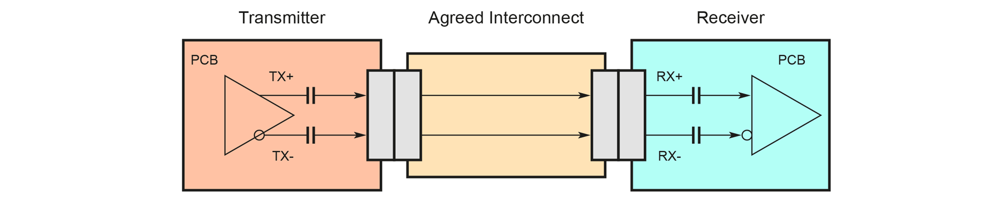
Figure 1. Data transfer line
Balanced alignment here implies matching of wave resistances (Impedance), as return losses are actually reflections of the signal caused by mismatching impedances at various frequencies of 300 MHz, 600 MHz, 2.4 GHz, 6 GHz (differential return loss), the level of the signal being transmitted (Output/Input differential voltage), general phase “flicker” of the clock and data signal (total jitter at connector clock-data), and many other aspects.
All these parameters are taken into account while designing PCIe or SATA devices. Integrated transceivers of PCIe and SATA controllers also use emphasis on the transmitting side and equalization on the receiving side. The approach allows to compensate for the distortion of signal occurring during its transmission over a real communication channel. In other words, PCIe and SATA controllers try to tune in to the data transfer channel by amplifying or attenuating various frequencies in the signal, and perform different adjustment tweaks both on the receiving and the transmitting sides.
PCIe and SATA interfaces are full duplex point-to-point links. The connection scheme for these interfaces implies connection between two Host and Device objects only as shown in the Figure 2.
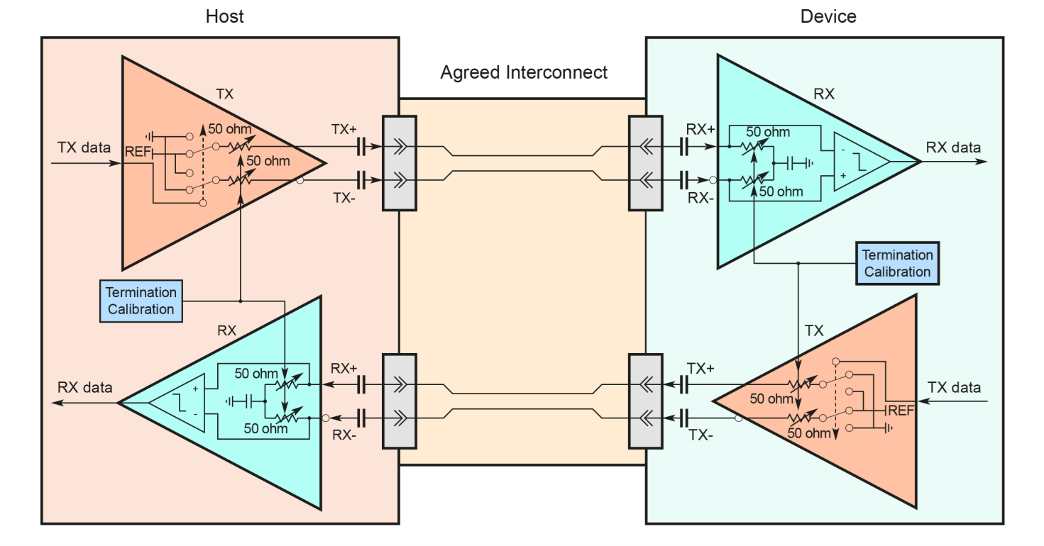
Figure 2. Real PCIe, SATA data transfer line
When standard devices from the product kit (SSD M.2 PCIe NVMe adapter, SSD PCIe x16 adapter, SAS adapter, etc.) are connected to the ports of PC-3000 Portable III and HDD/SSD SATA drives with the included SATA cables, the transmitters and receivers of the ports as well as data lines are completely matched in terms of their properties. However, such alignment may be lacking if third-party adapters are used. See, for instance, a set of adapters of Chinese manufacture: USB SATA FHDD UTS, Figure 3 or DFL Data Unlock Sata Connector, Figure 4.
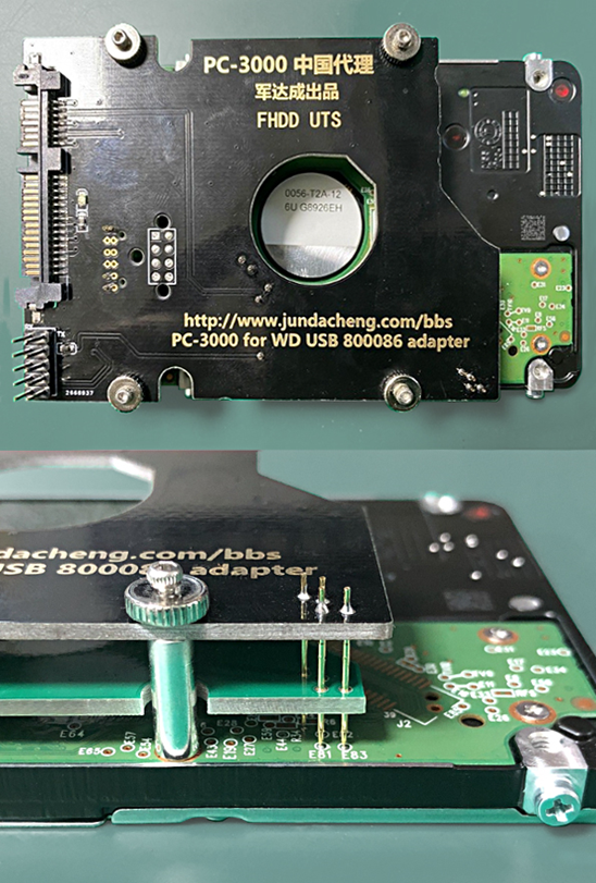
Figure 3. USB SATA FHDD UTS adapters set
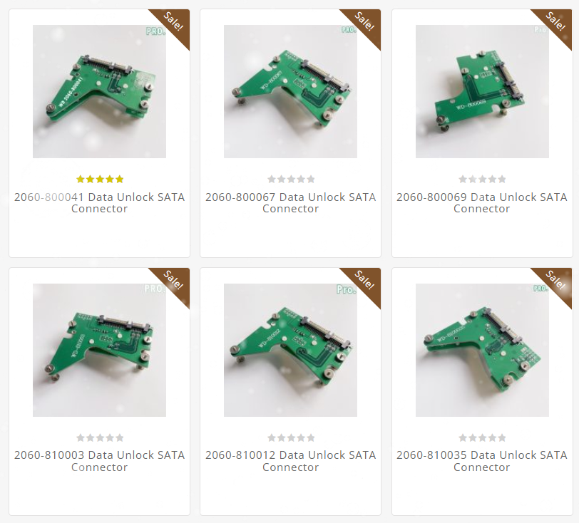
Figure 4. DFL Data Unlock Sata Connector
The set consists of PCB layout patterns corresponding to various WD USB HDD models with installed SATA and COM connectors, and a needle fixture for connection to the original PCB contacts of the drive being restored. They are mounted on top of the native PCB of WD USB HDD using screws. According to the manufacturers of such adapters, no need to solder 4 wires as a quick manipulation transforms a WD USB HDD into a WD SATA HDD. But let us see what is actually happening here, especially if a user forget to unsolder 4 capacitors on another PCB side. The SATA interface allows connection between two Host and Device objects only while the situation with a connected USB SATA FHDD UTS or DFL Data Unlock Sata Connector adapter is shown in the Figure 5.
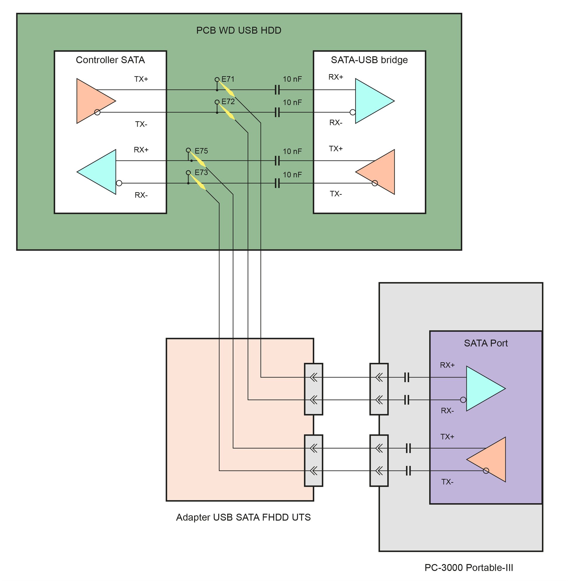
Figure 5. A WD HDD USB connected to PC-3000 Portable III with the USB SATA FHDD UTS adapter or with DFL Data Unlock Sata Connector
As we can see, the transmitter outputs of the SATA-USB bridge in the drive and the port of PC-3000 Portable III turn out to be short-circuited with alternating current passing through. As we know from the electronics course, shorting outputs is absolutely unacceptable if they have not been originally designed for such a connection, as it leads to transmitter overloads and possible damage to both the SATA-USB bridge transmitter and the PC-3000 Portable III port transmitter. The SATA output of the HDD controller also turns out to be linked to two receivers connected in parallel (SATA-USB bridge and PC-3000 Portable III port), resulting in an overload of the SATA transmitter within the HDD controller and its likely damage. At the same time, a complete misalignment of all parameters occurs within the differential lines receiving and transmitting interface data. When the power is turned on, the initialization process is started on the physical level of the SATA interface, the Host and Device begin to “negotiate” the transfer rate, try to adjust the channel to acceptable characteristics, and then generation of the PHYS signal follows. But what happens when three devices are on the same line, how can they negotiate? Most likely, the device with more powerful transmitter will suppress the weaker device with a high probability of damage to its ports.
Besides the adapters mentioned above, there are other solutions, for example, the ones shown in the Figure 6.

Figure 6. SATA adapter for solder connection
The adapter implies soldering of differential data lines and power lines directly to the drive’s test points. They are even specified on the adapter as E71, E72, E73, E75, however, there is no indication that desoldering the capacitors on the HDD board from the USB bridge side is mandatory. Otherwise, we end up with a situation exactly resembling Figure 4 with unstable operation and likely damage to the port of PC-3000 Portable III.
Conclusions
- PCIe and SATA high-speed serial interfaces implemented in the controller of PC-3000 Portable III require matching between differential pairs, which must be kept in mind while connecting nonstandard devices. In the best case, such misaligned connection will slow down the work, otherwise it may damage the port of PC-3000 Portable III. Connection of devices that are less than reliable is best avoided.
- While working with USB HDD and, if necessary, converting them to SATA, using a compatible SATA board of that family is recommended (most drive families are produced in two versions – SATA and USB) [1]. The exception is WD USB hard disk drives SED (Self Encrypted Drive). For them, when adapting a compatible SATA board, it is necessary to transfer not only the ROM chip, but also the microprocessor, because it contains unique encryption keys.
- If a SATA connector is soldered or connected directly to the SATA controller of the USB drive’s PCB, then it is obligatory to unsolder the four capacitors connecting the USB bridge and the SATA controller on the HDD board [2].
- Damage to the ports of the PC-3000 Portable III controller during manipulations with USB HDD converted to SATA resulting from using USB-SATA adapters of Chinese manufacture without soldering (without unsoldering the capacitors connecting the USB bridge and the SATA controller on the HDD board), or any other adapters that do not provide for the properly aligned connection of the SATA interface is not covered by the warranty.
[1] – For details on using a compatible SATA PCB for WD USB HDD, please see the documentation in “002_Western Digital Marvell USB COM (2010-20xx).pdf”, section 4.3 “Installing a compatible SATA board”.
[2] – For details on soldering a SATA connector onto the board of a WD USB HDD, please see the documentation in “002_Western Digital Marvell USB COM (2010-20xx).pdf”, section 4.2 “Adding the SATA connector”.
Although the above-mentioned FHDD UTS or DFL Data Unlock Sata Connector adapter is no worse than other boards but more convenient in terms of usability and allows to connect the drive faster, it is strictly required to unsolder the four capacitors connecting the USB bridge and the SATA controller on the HDD board.
Recommended reading on the topic:
https://www.testandmeasurementtips.com/multi-gigabit-serial-protocols-demystified/
UPDATE: Starting from 2024, all Portable III and Portable PRO kits contains a new SATA Port Protector! It’s strongly recommended to use this protector before connect any third-party SATA adapter! Please note that this SATA Port Protector is compatible only with SATA-based drives (SATA, mSATA, M.2 SATA, etc) and not compatible with PCIe / NVMe drives.
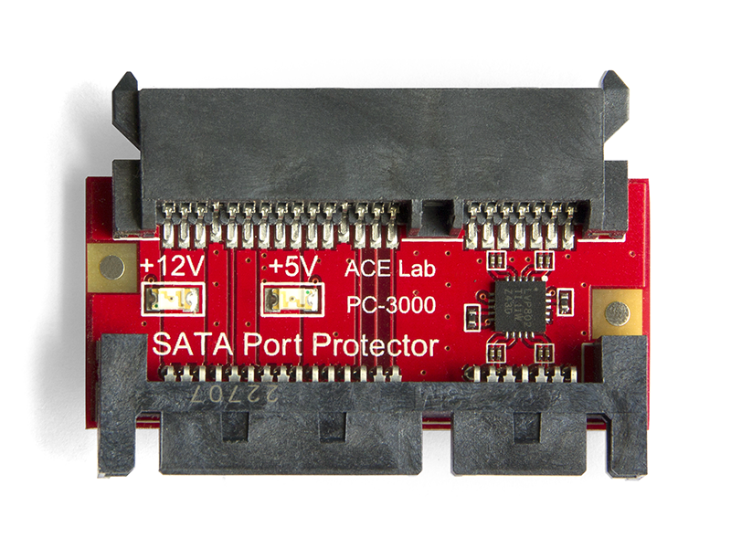
SATA Port Protector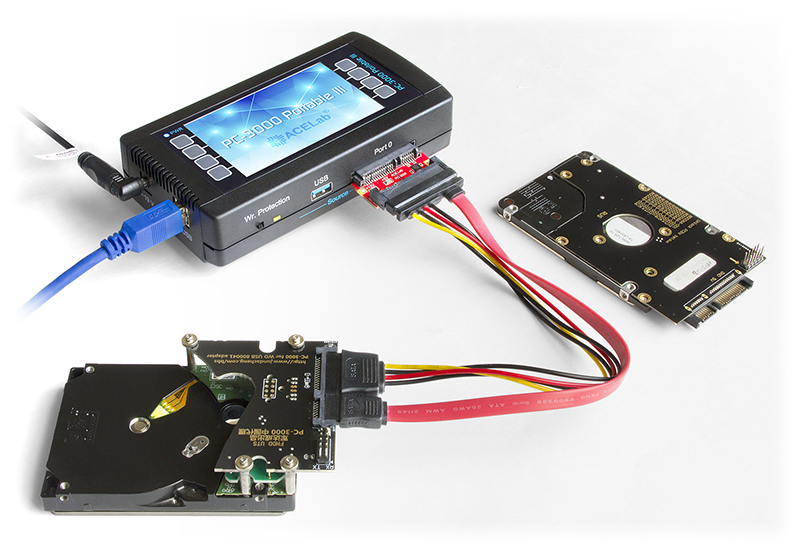
Chinese USB to SATA PCB for WD SMR drive connected through SATA Port Protector


 (6 votes, average: 3.67 out of 5)