

Dear friends,
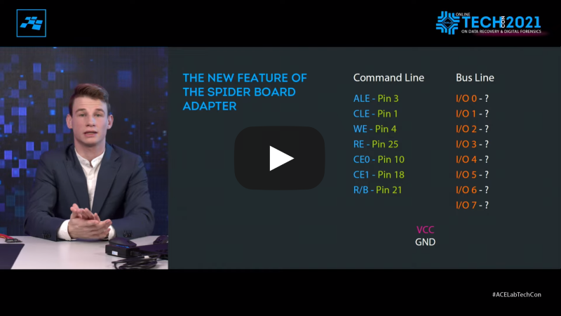
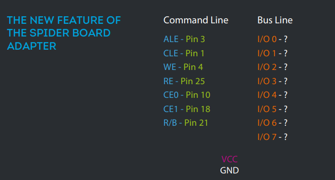
If you have ever dealt with monolithic data recovery, you have definitely faced the necessity to find out the order of the bus line pins. Previously, if you had not known the order of the bus line pins and if you had no pinout map with all the information – such a case could not have been solved. But now things are easier with the new feature we showed at the ACE Lab Online Technology Conference 2021. From here on, with the Spider Board adapter and the latest PC-3000 Flash software update 7.5.11 you will be able to find out the order of the bus line pins!
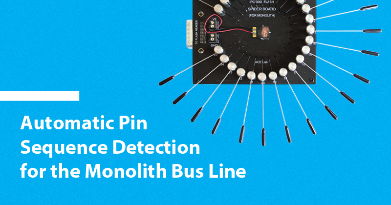
A couple of words on the Spider Board adapter:
The PC-3000 Flash Spider Board adapter is a universal solution for safe monolith recovery without tedious soldering! Using it, you don’t need specific adapters for each monolith you deal with.
Since March 2017 when the Spider Board adapter was released, it has become extremely popular as a smart tool for easier and faster data recovery from monoliths. You can also visit this link to learn how to use this adapter and to learn more about its capabilities.
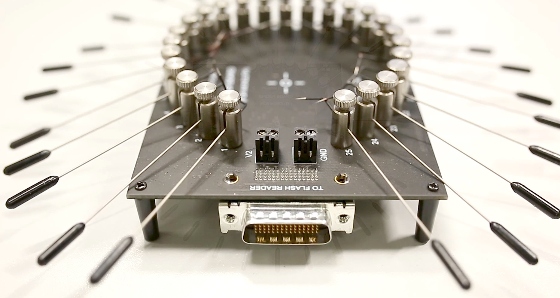
The Spider Board adapter is designed for connection to internal contacts of NAND-based Flash drives manufactured as single-package chips (monoliths). The adapter consists of 25 universal contacts that support the software configuration of their association with NAND interface signals in a corresponding task.
Please note: the Spider Board adapter is supported by the PC-3000 Flash Reader 4.0 only.
The Spider Board adapter already has a lot of features that can ease your work with monolithic devices, but there is no limit to perfection! That’s why our developers have added the new feature of automatic detection for bus line pins order.
This feature will be very useful when you are exploring the monolith pinout and manage to detect the position of command line pins and bus line pins. You can do it pretty easily if you use the oscilloscope for this task. The command line and bus line pins have a specific type of signals that can be determined on the oscilloscope.
So, let’s imagine that you find out where the command line and bus line pins are situated on the monolith. What’s next? How can you be sure about the order of the bus line pins? You can try to iterate over different variations of their order, but there are so many of them that it makes it almost impossible to get the right option.
That’s when our new method comes to the rescue. Let’s specify what you need to do in order to get the Chip ID, read the dump and continue with data recovery from your monolithic device.
Feel free to watch the video of the process or continue reading the step-by-step guide:
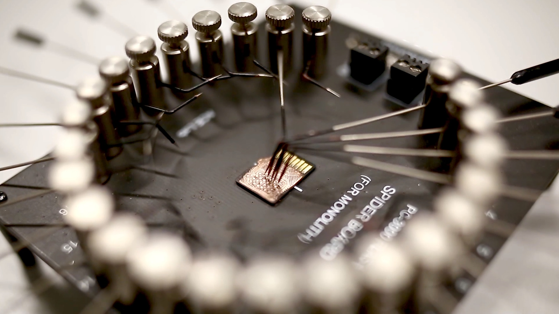
Step 1. Find out where the command line pins are.
Step 2. Find out where the bus line pins are. Don’t waste your time on trying to find the right order! Just set the needles on bus line pins and you are ready to go.
Step 3. Launch the PC-3000 software and follow the screenshots below:

Start with the “Adapters Params” button to open the window for the Spider Board parameters.
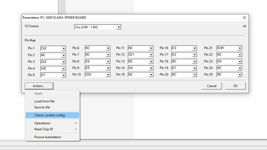
Use the “Check current config” feature to check if you have a good contact on all your pins.
As you can see from this screenshot, the command and bus line pins are selected, but the order for the bus line is wrong.
If you see the same results, it means that there is a good contact on each pin, and you can proceed with the next step.
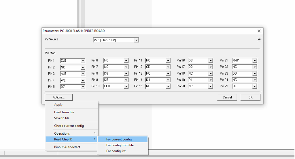
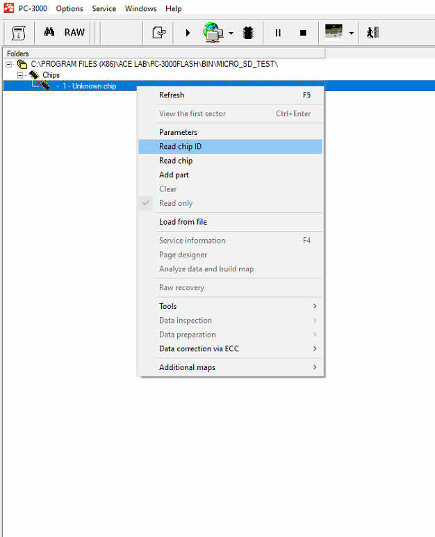
Select our new feature – “Read Chip ID” – > “For current config” to set the autodetection for the order of bus line pins.

Keep these two options “on” and continue.
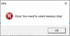
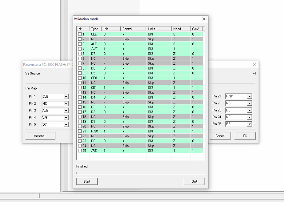
Nevermind that such a window may pop up during the process. It is normal for this process. Just press “OK” and wait till the end.
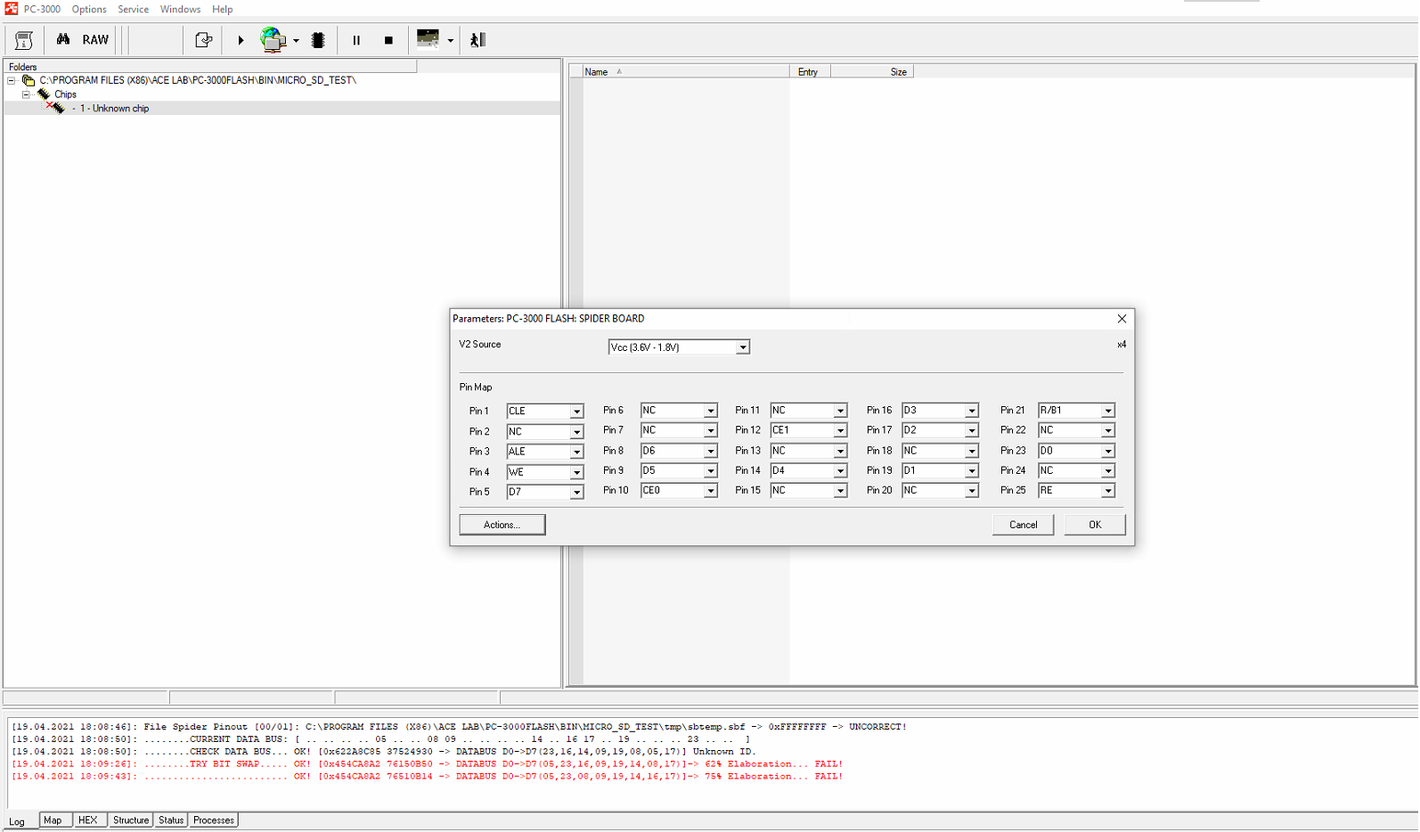
This is what you should see in the log at the end of the process. There will be a couple of messages about the right order of the bus line pins. Please choose the variant with the biggest percentage. In our case it will be the last line in the log.

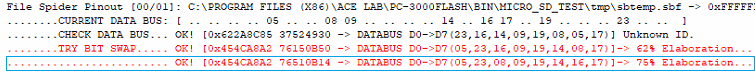
Please use the last line in the log and change the order of the pins in the window.
In this case:
D0 = Pin 5
D1 = Pin 23
D2 = Pin 8
D3 = Pin 9
D4 = Pin 19
D5 = Pin 14
D6 = Pin 16
D7 = Pin 17
When you change the pins, press “OK” in the Spider Board Parameters window and go to the main window to “Read chip ID”.

Wait until the PC-3000 Flash software autodetects the Chip ID, and continue with recovering data.
In conclusion, let’s summarize what has been added.
- We should know the position of all the Command Lines (ALE, CLE, RE, WE, R/B, CE);
- We shoud know which pins belong to the Bus Line (but the sequence is not important);
- Power Supply must be soldered on the monolith main interface (mSD, SD, USB);
- The current detection works only with 8-bit Monoliths. 16-bit modifications are very tricky, rare and are not supported at this moment.
Now, there is no need to waste your time searching for the right order of bus line pins by yourself. Just put the needles on the bus line pin, start the new autodetection method and the will do everything by itself – you will just need to enter the correct order at the end of the process.
If you have any questions do not hesitate to ask ACE Lab technical support service for assistance.

