

Hi everyone,
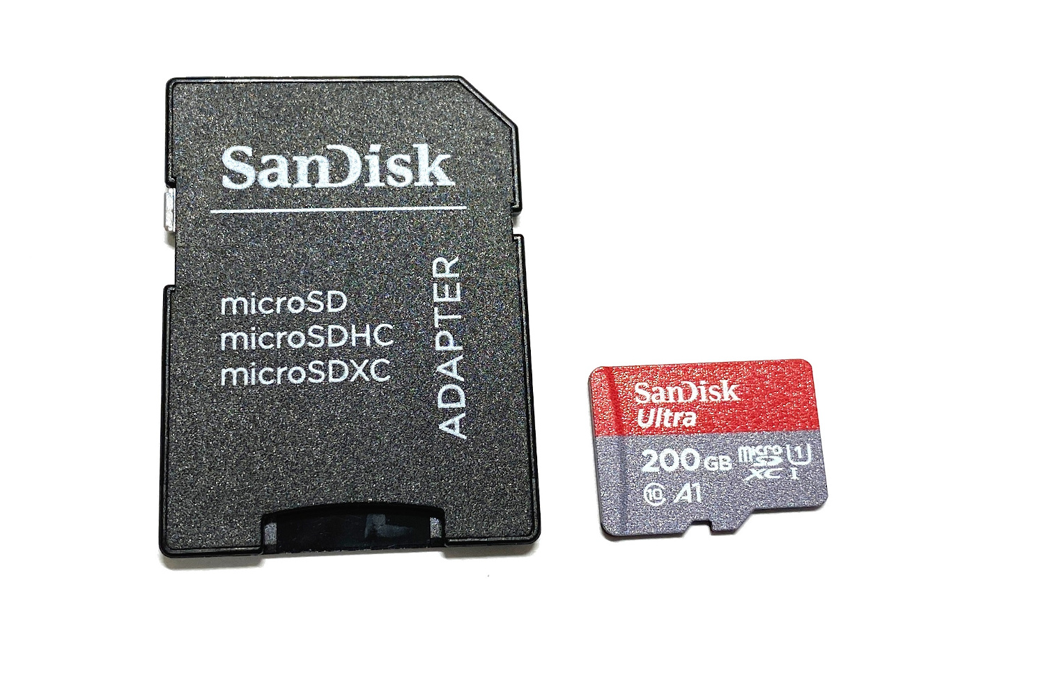
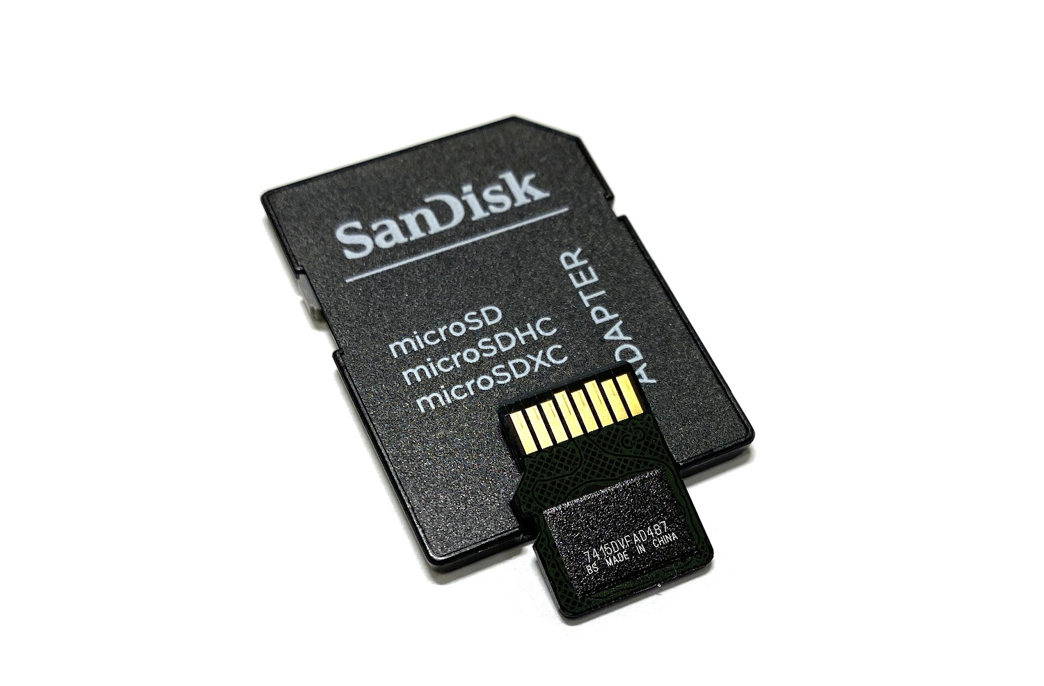
Today we are going to talk about the monolith cases produced by SanDisk, namely presented in the variations of 200 GB and 400 GB models.
 Such cards were released a few years ago and remained the mSD cards with the highest capacity for years until the 256 and 512 GB modifications replaced them.
Nowadays, SanDisk Flash drives are one of the most complicated cases. Usually, they have a lot of additional issues and features that are typical only for SanDisk modifications.
For example:
-
SanDisk is using SLC cache to store the latest recorded data. On MLC/TLC memory, the controller writes down data in SLC mode, and then in the background transforms it into TLC/MLC. The main idea is that with the SLC recording type, SanDisk is using around 20-30% of capacity for cache, which makes writing operations much faster than usual. If the Flash drive becomes damaged during the writing process, most likely the File System and the latest recorded files will stay in SLC and their recovery will be impossible. The only way to recover SLC cache is to use a translator.
-
The SanDisk controller is using subblocks for updating the file system. That’s why when we apply image building with Block Number Type 1 [0000], we can get only a partial File System or even an empty image. For recovery of the Folder Structure, in 90% of cases, we need a translator.
-
Videos are also connected with the File System, and they are seriously fragmented between blocks and subblocks. And again, the only way to recover it is to use a translator.
-
Without a translator, it’s impossible to assemble an image with a Block Number if the case capacity is bigger than 64 GB. Service Area marker includes only 2 bytes without a bank marker, so the maximal number of sorted blocks is around 64 GB. 128 GB cases and above will be supported only by the translator.
In this article, we will look at SanDisk’s 200 GB solution.
At one time, such drives were a technological breakthrough. Very capacious mSDs were put into top-end cameras and smartphones.
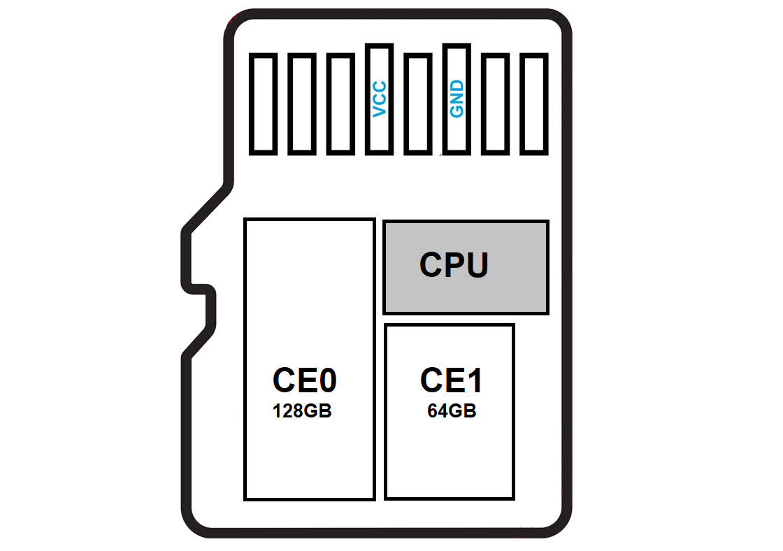
What makes this monolith special is that it has two crystals, one of 128 GB and the other of 64 GB. Because of the difference in the capacity of the parts, we will need to read each chip separately in different tasks to combine them into one later.
So, let’s start working with the monolith.
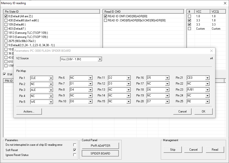
Pay attention to the monolith. Most likely, it corresponds with Type 1 pinout scheme from the monolith database in the Global Solution Center.
Next, we need to strip the top layer of the monolith with a medium-hard fiberglass pencil.

As we can see after stripping, we were right and the pinout of the monolith matches the Type 1 pinout scheme.
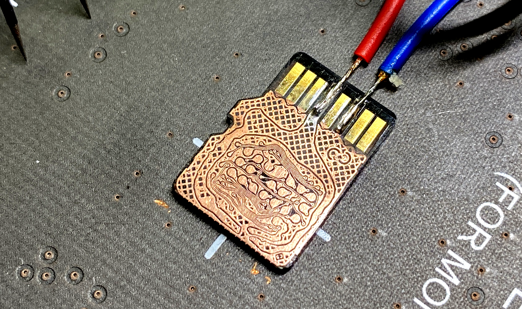
Let’s solder the power wires to the pins of the monolith according to the mSD Type 1 pinout scheme.
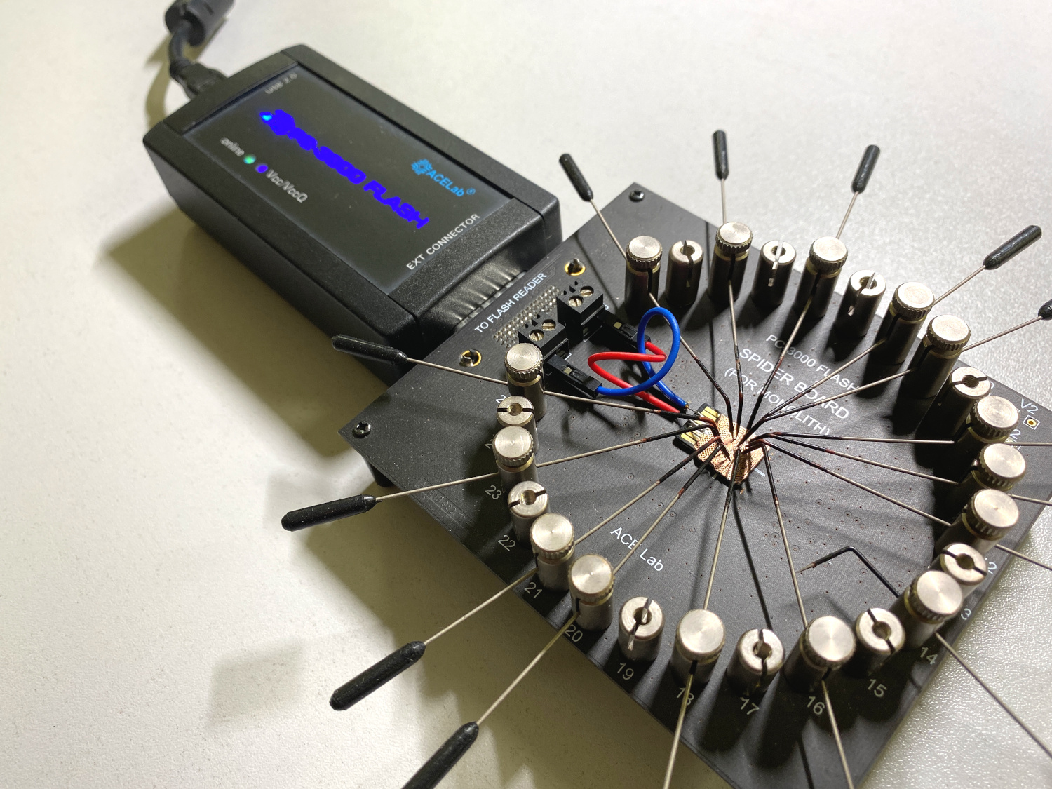
Put the monolith to the Spider Board pad with double-sided adhesive tape, connect the power wires and set all the pins according to the scheme.
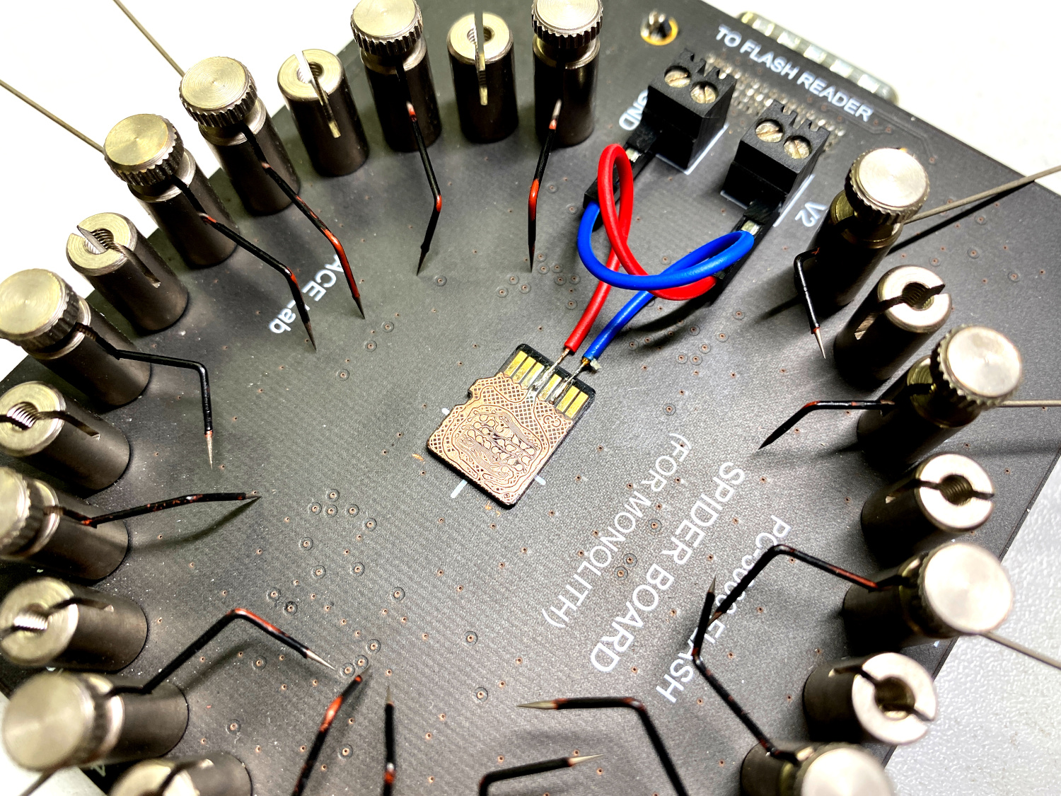
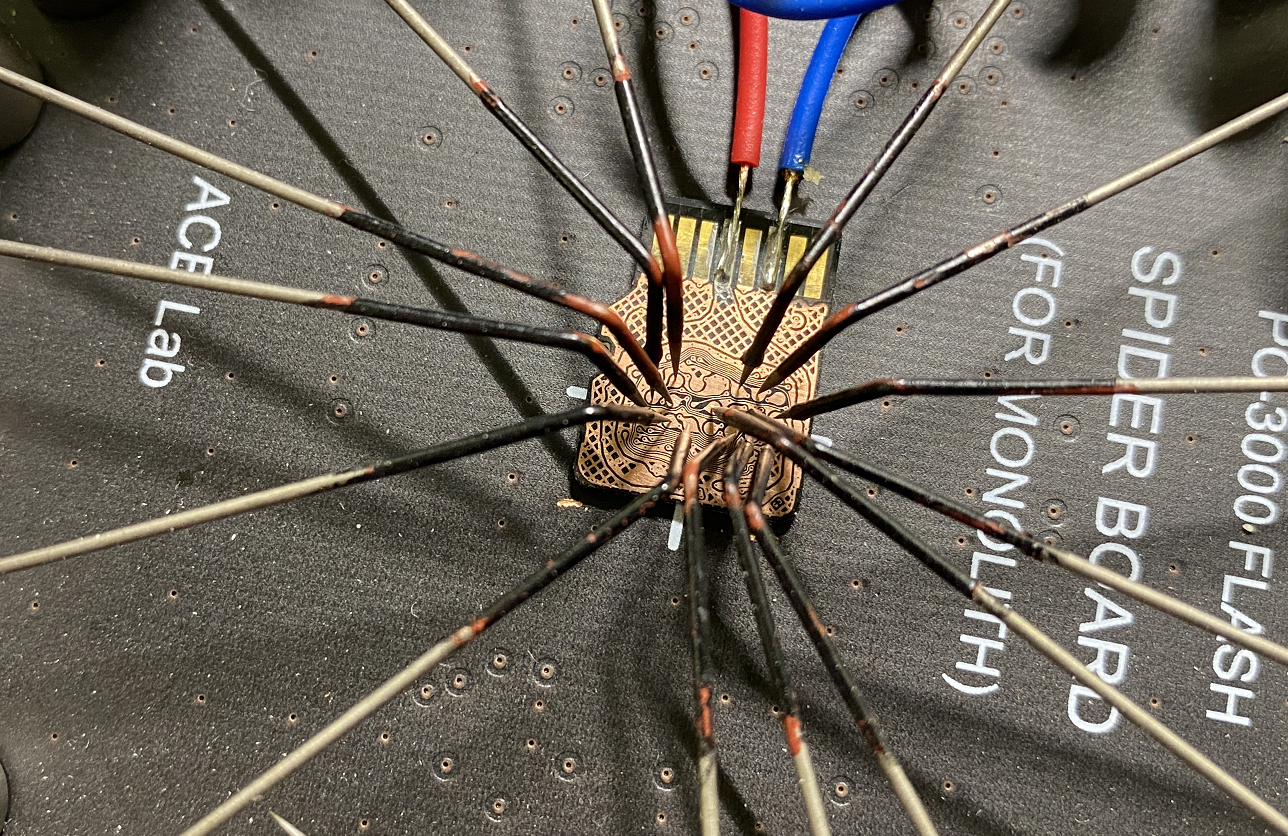
So, all the preparation steps are completed, and we can move on to the program part.
Step 1.
We need to read the first part of the 128 GB monolith. To do this, we will set the Spider Board pin to CE0, while CE1 will stay inactive.
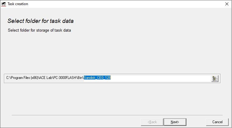
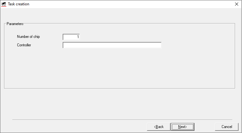
Then we create a task with 1 physical chip (for CE0), set pins in the software and read it to the dump. It’s going to be a 128 GB part.

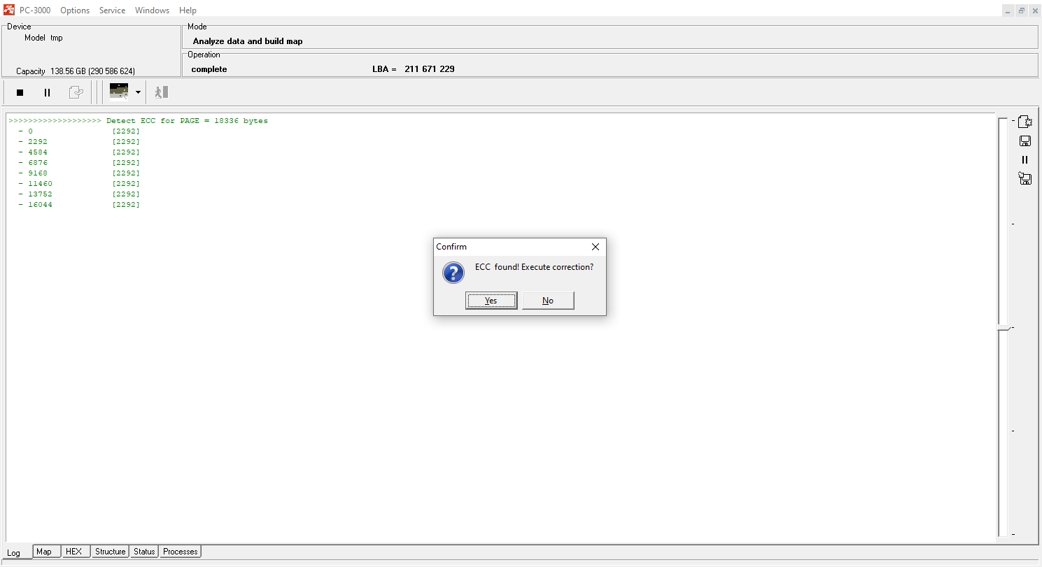
After successful reading, we perform ECC correction. Also, you should not forget about the rereading to get the best quality of the dump.
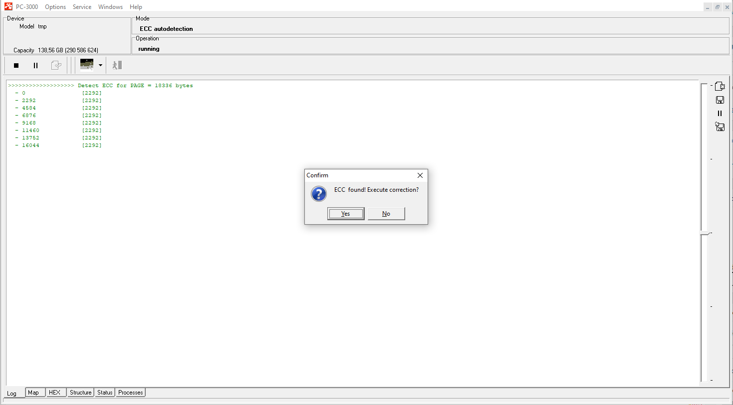
NOTE We strongly recommend to always perform the ECC correction on the graph only (not on chips).
Step 2.
To work with the second 64 GB part, place the Spider Board pin on CE1, while CE0 should stay inactive. Create a new task and do the same with the second part of the monolith with 64 GB capacity.

Please note: we need to get the best possible dump quality on each part to get good recovery results. That’s why we should pay attention to the bad sectors. During the rereading, sort all the uncorrected chains from the small value to the high value.
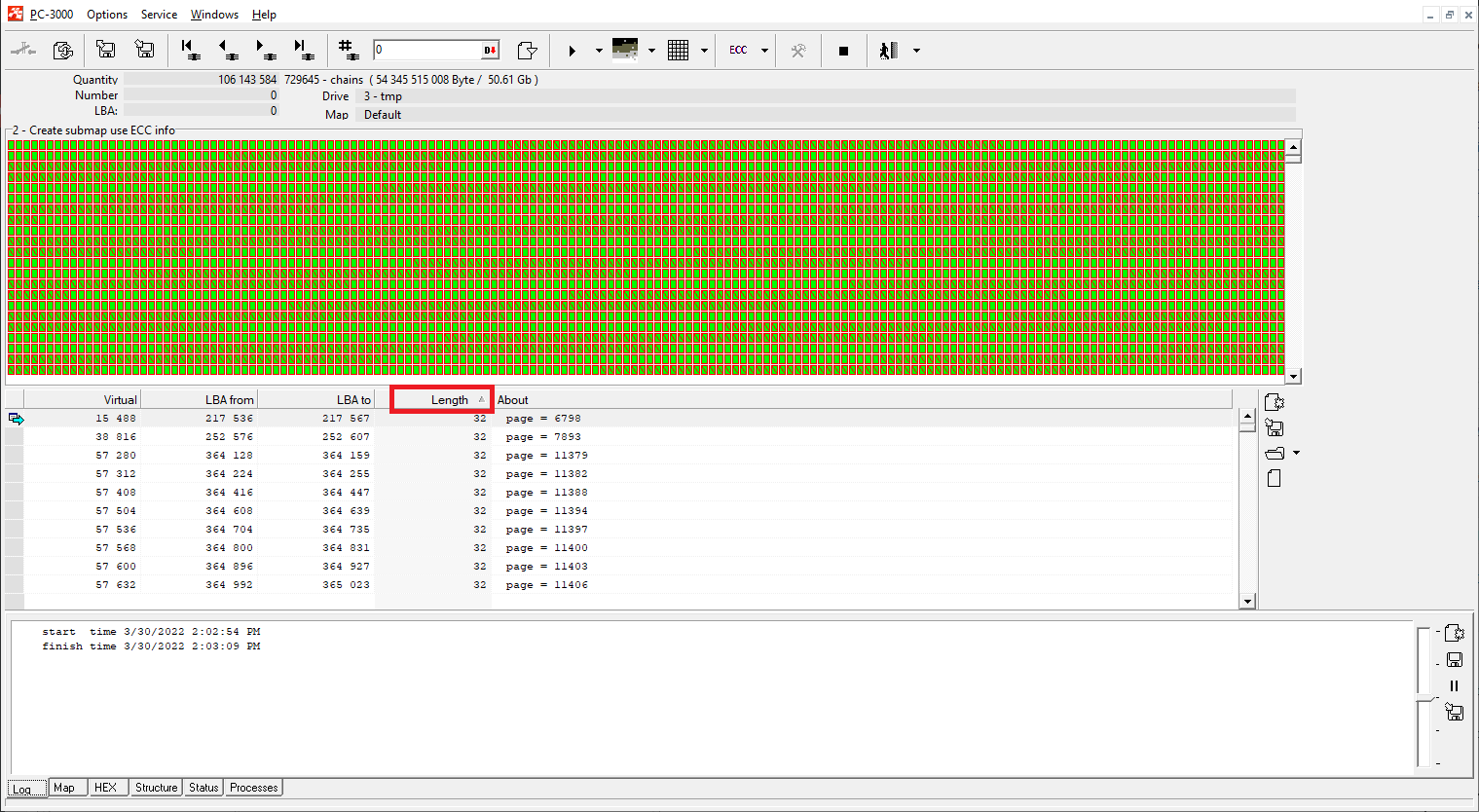
It’s important because we need to fix as many small chains as possible – they are located around the dump and may seriously affect the file quality and further translator assembling.
Step 3.
Then we need to merge both parts of the monolith into a single task.
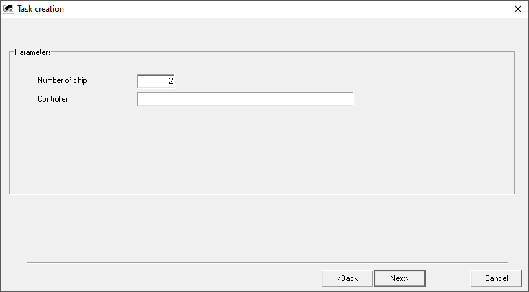
To do this, we create a new task with 2 physical chips.

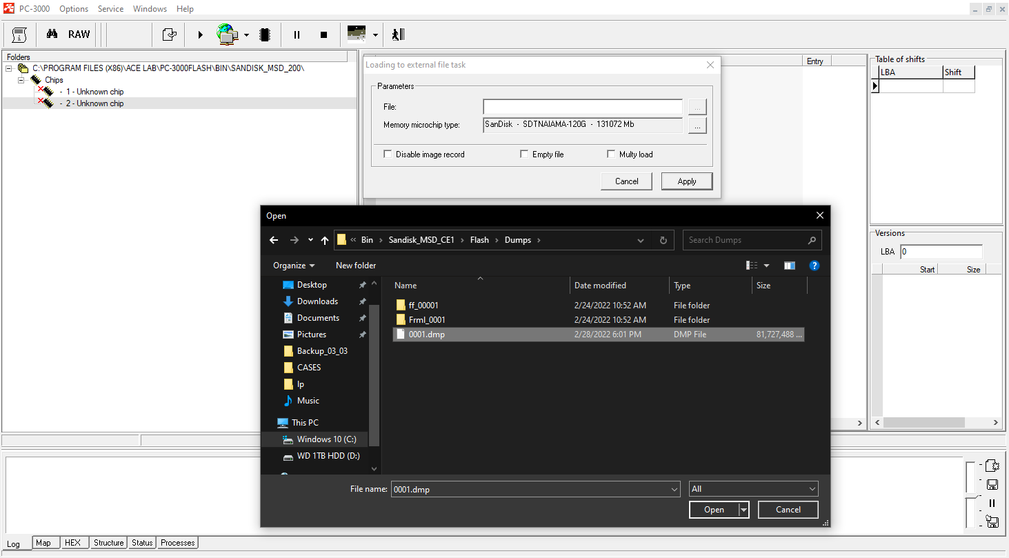
Using loading from the file, we choose the appropriate ID for the first chip (we take the ID from the first task – ID for 128 GB SanDisk NAND) and also choose the dump file from the first task for loading.

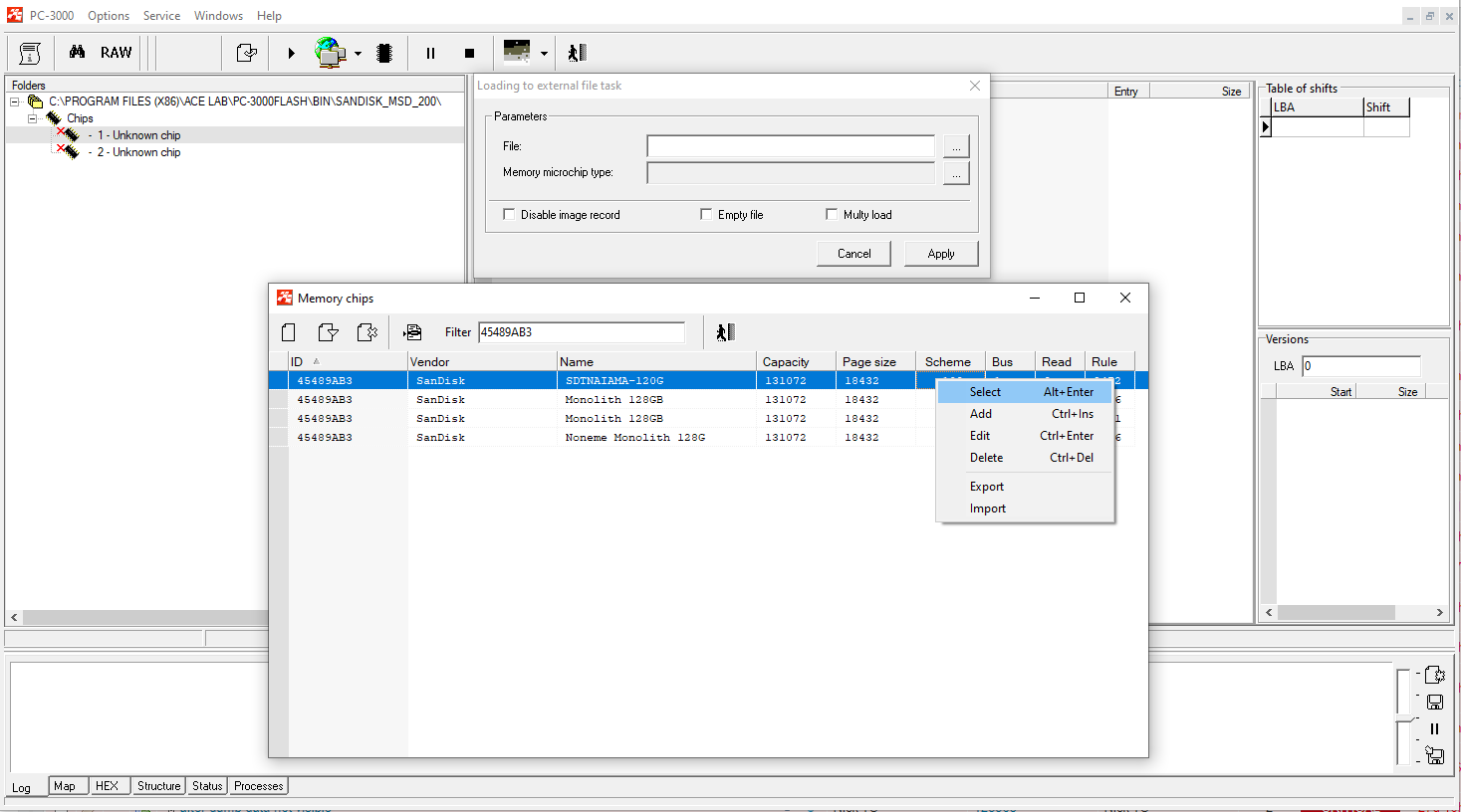
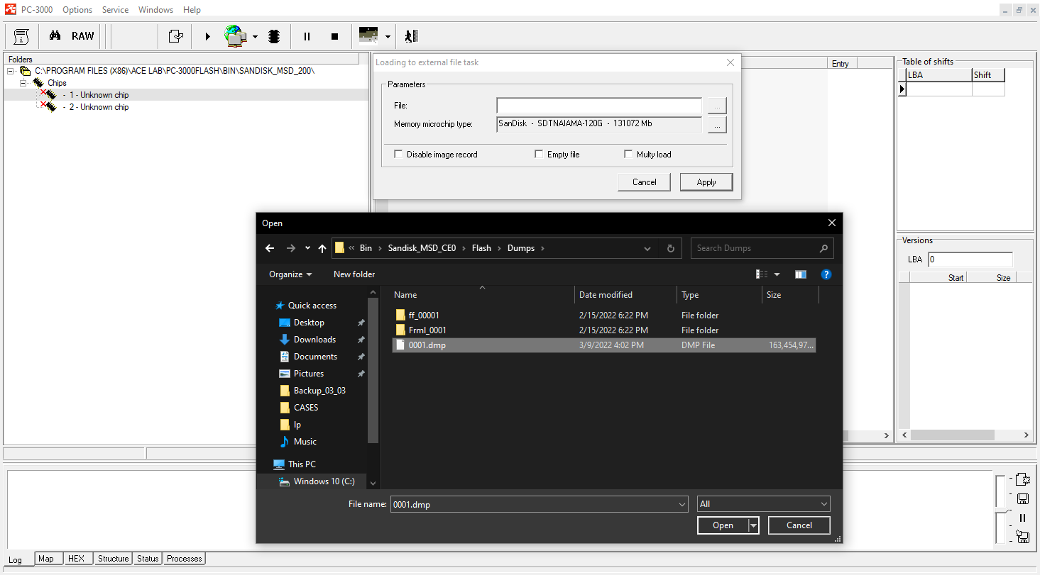
In the second chip, we leave the same ID as in the first one and load the dump from the second task.
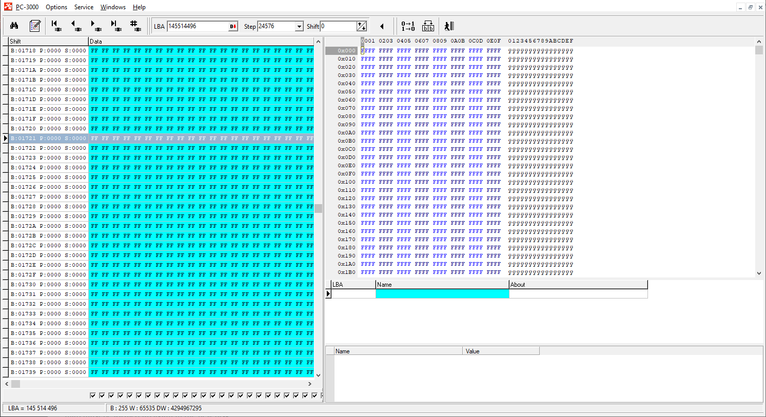
So, we got the task with 2 parts of our monolith.

The capacity of each chip corresponds with 128 GB (256 GB total). As we can see, the second chip will be half filled with FF, because its actual capacity is 64 GB.
Let’s update the chips and add a transformation graph to proceed with preparation steps.
Step 4.
Now we need to launch the ECC correction again to create a new map of sectors status. We already fixed the ECC and did rereading before, but for a good translator assembling, the ECC map needs to be formed up again in a new task (the translator is using information about good and bad sectors):

Step 5.
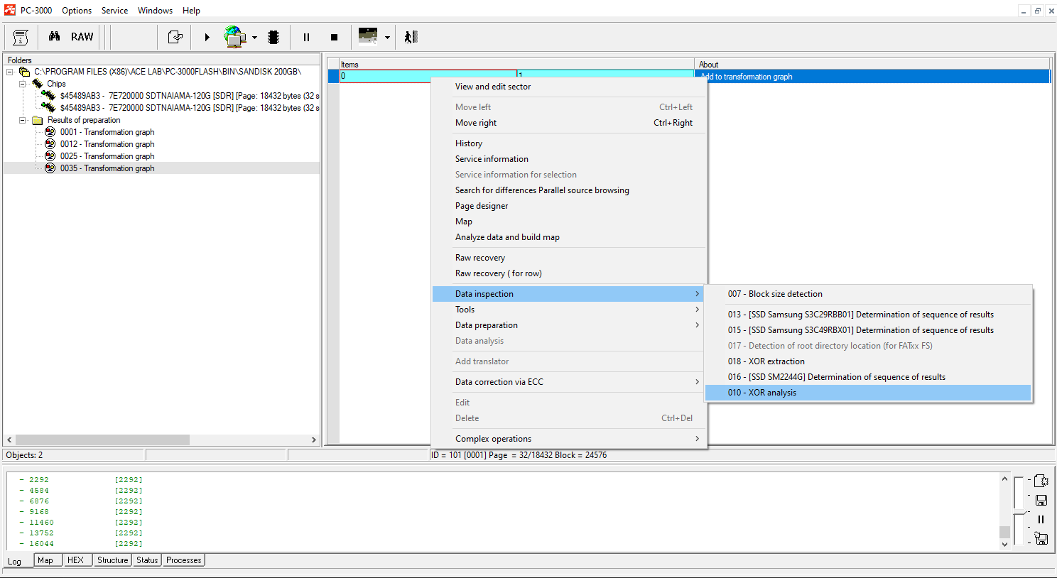
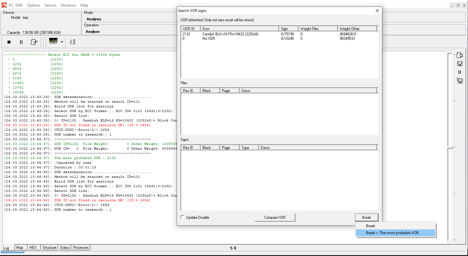
Detect the right XOR and apply page transformation.
With SanDisk cases, Page Transformation should be done manually, using the following rule: each ECC range contains 14 bytes of SA in the beginning, then 4 ranges with data and finally – ECC codes. Here is how we need to set the page transformation: 14SA + 512DA+512DA+512DA+512DA+230ECC
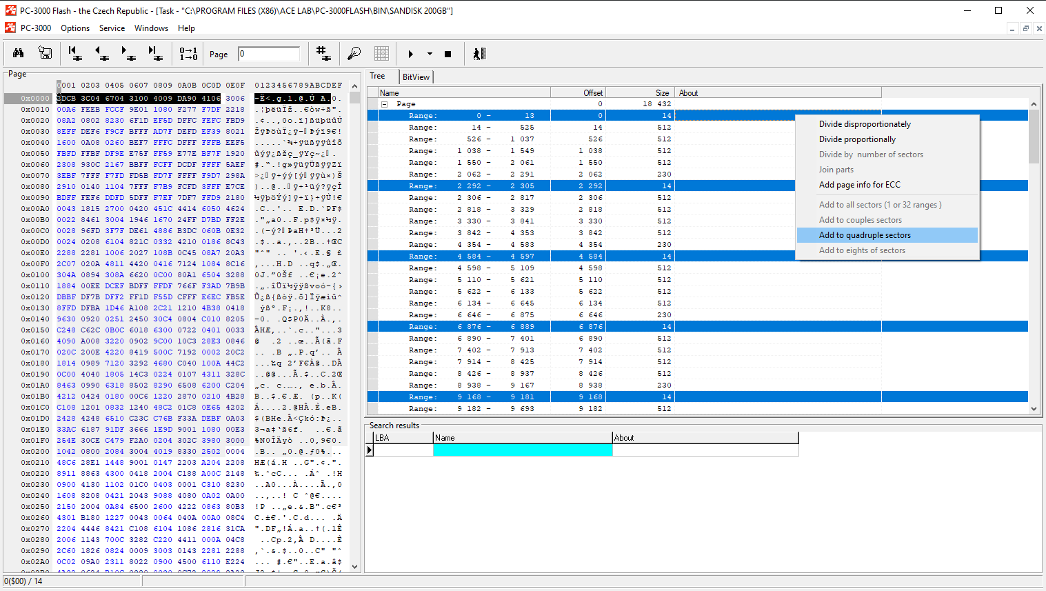
It is typical for SanDisks that the SA part includes 14 bytes which come from the beginning of the page.
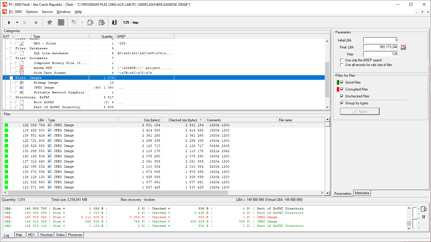
So, to check whether the applied XOR and page transformation is compatible, we try to apply Raw Recovery on the last graph string:
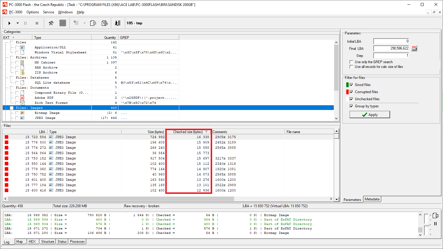
As we can see, there are a lot of files with the checked size bigger than the page size. This means that the data integrity has increased after this preparation.
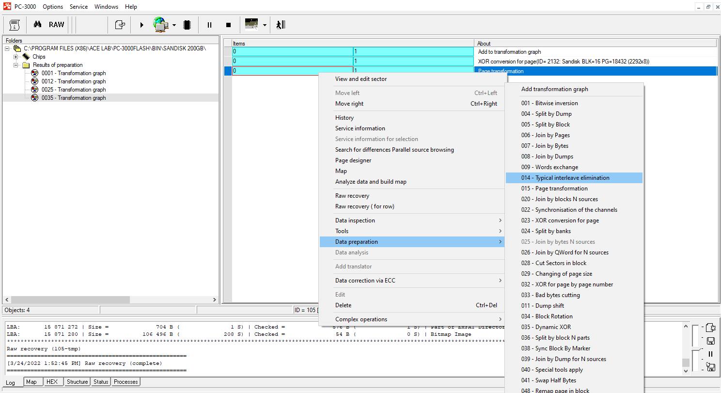
Step 6.
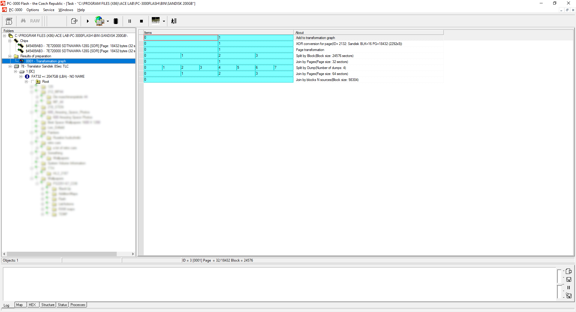
In this case, we will need to perform only one Typical interleave elimination (Split by Block; Join by pages).
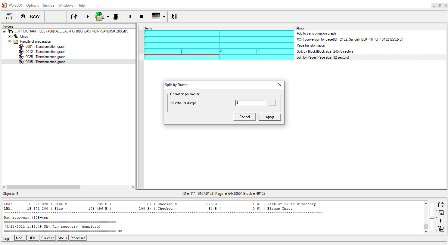
Step 7.
Following up, we split dumps (the software will select the number of dumps for splitting automatically, it depends on the number of LUNs inside the NAND):
Step 8.
Join the result with external interleave (Join by pages):
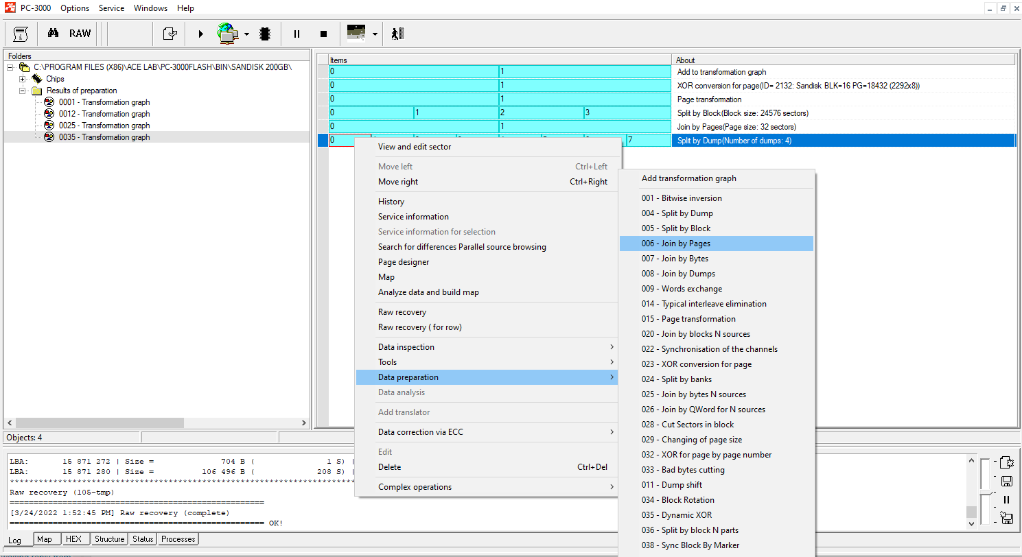
Step 9.
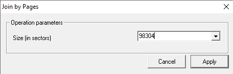
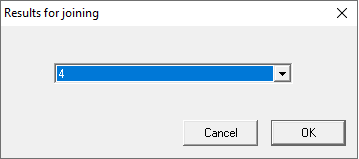
The next step we need to take is to use Join by Block N sources.
The size of a block is 98304. The number of results for joining is 4.
Note a good result of RAW recovery on the last graph preparation!
Step 10.
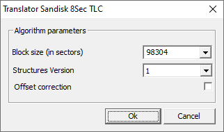
The final step of our recovery will be to assemble the image.
As we managed to get a good quality dump, the best possible way to build an image would be to use the SanDisk 8Sec Translator for TLC chips.
The translator will take into account the SLC cash and add-on blocks, and we will get a complete high-quality file structure.
After all conversions, the file structure after image building looks pretty good. We can see numerous files and folders which can be saved and used without problems.

SanDisk memory mSD and SD cards are very popular, and the PC-3000 Flash contains the widest range of tools for good image reconstruction. The described steps might look complex for beginners, but with the help of ACE Lab TS engineers, it will be possible to solve even the hardest tasks!
If you have any questions regarding your data recovery cases, you’re welcome to address them to the ACE Lab Technical Support department.


 (7 votes, average: 3.86 out of 5)
Good job, thank you very much.
Excellent information..
Cheers!
Wow, it’s impressive to see how PC-3000 Flash can successfully recover data from SanDisk 200 GB microSD cards!