


Hello everybody!
Last week we have discussed how to make the first steps in NAND Flash data recovery with the PC-3000 Flash during the ACE Lab Free Webinar. Following up, we have prepared for you this article about the vital procedures for recovering Flash cases. This topic will be especially interesting for beginners in NAND Flash data recovery who want to learn how to deal with NAND Flash in the most efficient and the smartest way. For already experienced data recovery specialists, this article can serve as a handy checklist on the main data correction methods while dealing with Flash cases.

Firstly, we are going to discuss ECC Correction and Rereading of invalid sectors.
Part 1. Theoretical. ECC.
During NAND memory chip reading, some bit errors may appear. The number of bit errors depends on the following factors:
►Type of the NAND memory chip (SLC, MLC, TLC, QLC)
►Cleanliness of the contacts (dirty chips are usually read worse)
►Temperature influence (high temperature during chip unsoldering may damage cells)
►Wear level of NAND cells (if the information on a NAND device was rewritten several hundreds of times, the quality of small cells-capacitors decreases, and they are read with a lot of errors)
►Low quality of the chip (Nowadays manufacturers often cut production costs by using, for example, a small tech-process to compress the size of a cell, resulting in errors appearance in new Flash drives)
If you want to get the maximal recovery rate from a Flash drive, first of all, you need to fix as many ECC errors as you can. Otherwise, all the data will be corrupted, not workable, or partially damaged:

The basic way of error correction is the ECC algorithm – the simplest way of data fixing. Usually, the controller puts into each page additional information, which is called Spare Area (SA). It contains some markers (for example, the marker for image building), different flags, and Error Correction Codes (ECC). ECC is special extended data based on initially written by the user information. This extended data helps to look for bit errors in sectors/ranges and to fix them through a special mathematic formula. Usually, ECC codes have a special length – the number of bytes selected for error correction. The largest number of ECC bytes allows you to fix more errors in each sector/range.
Common MBR sector from an old SLC NAND chip with 2112 bytes page size and 528 bytes sector size:
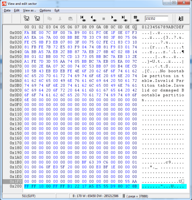
Yellow – our DA (512 bytes)
Blue – our Marker of Block Order in the logic image (6 bytes) of Block Number for image building
Green – Error Correction Codes (10 bytes):
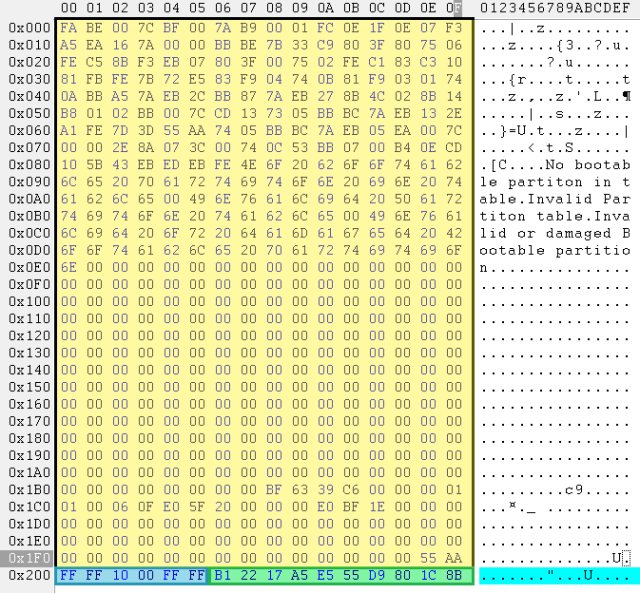
The PC-3000 software is trying to find all the bit errors in the following sector:
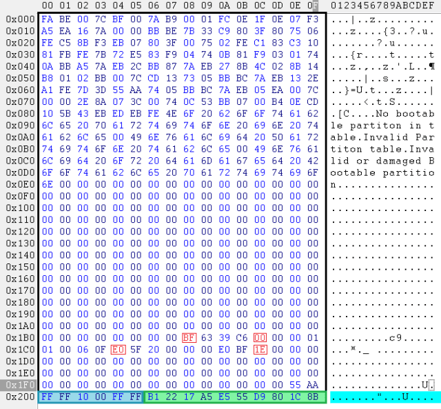
And it is applying ECC codes for error fixing:

Let’s move on to practice.
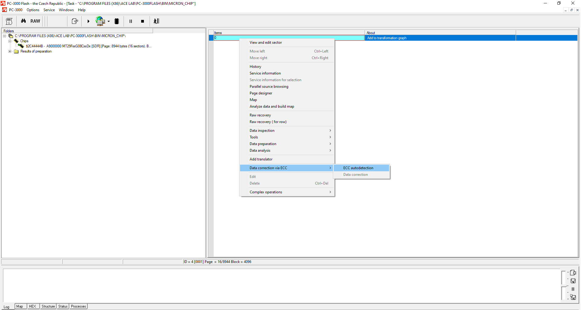
We have a Micron chip, 4GB capacity, chip ID: 0x2C44444B
We strongly advise you to autodetect ECC on the transformation graph ONLY (not on the chips). Different errors can occur when you correct ECC on the chips. Don’t waste your time correcting ECC on the chips (left part of the screen under the Chips node).

Though, it’s not always that easy to detect ECC.
In some cases before detecting and correcting ECC, you should check your dump for bad bytes or apply XOR (mostly for ITE, SSS, AU controllers), and only after that detect ECC on the graph. If we speak about old SLC and MLC NAND cases, ECC correction won’t be possible until you make the Page Transformation.
Part 2. Rereading.
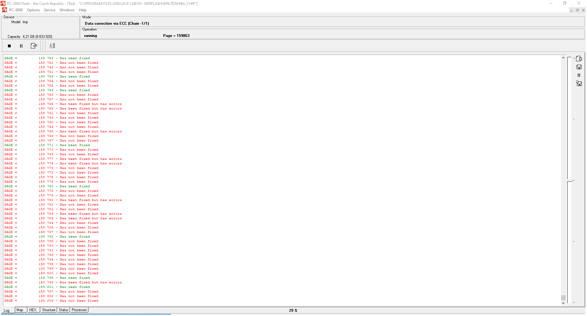
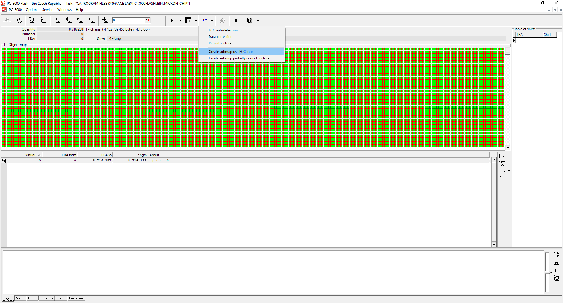
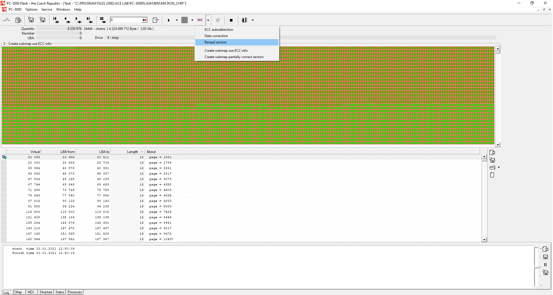
From the example below, you can see that the ECC correction is not going pretty well in this case. The correction quality depends on many factors – and that’s why when ECC correction ends, you should always build the map using ECC info to check how many sectors have still not been corrected.
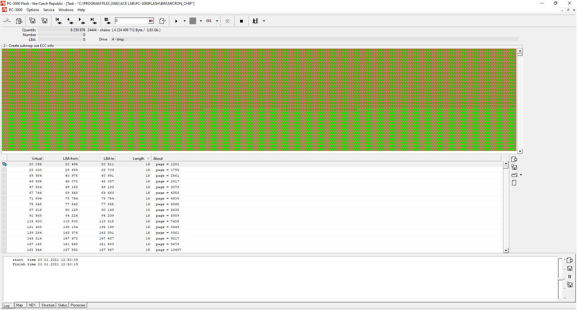
As we can see from the screenshots, we have 3.93GB of invalid sectors out of 4GB. It means that the whole dump is covered by errors. Each file will be corrupted. To get a good bit error raw recovery result, the error rate should be less than 5%, and the number of chains should be less than 100-500. If you didn’t pay attention to the number of chains, you can face the fact that your files are corrupted despite the fact that you have only several MB of errors.
And this is the part where Rereading should come in handy.
We need to start fixing the remaining after ECC correction bit errors with an additional data correction method – the Readout.
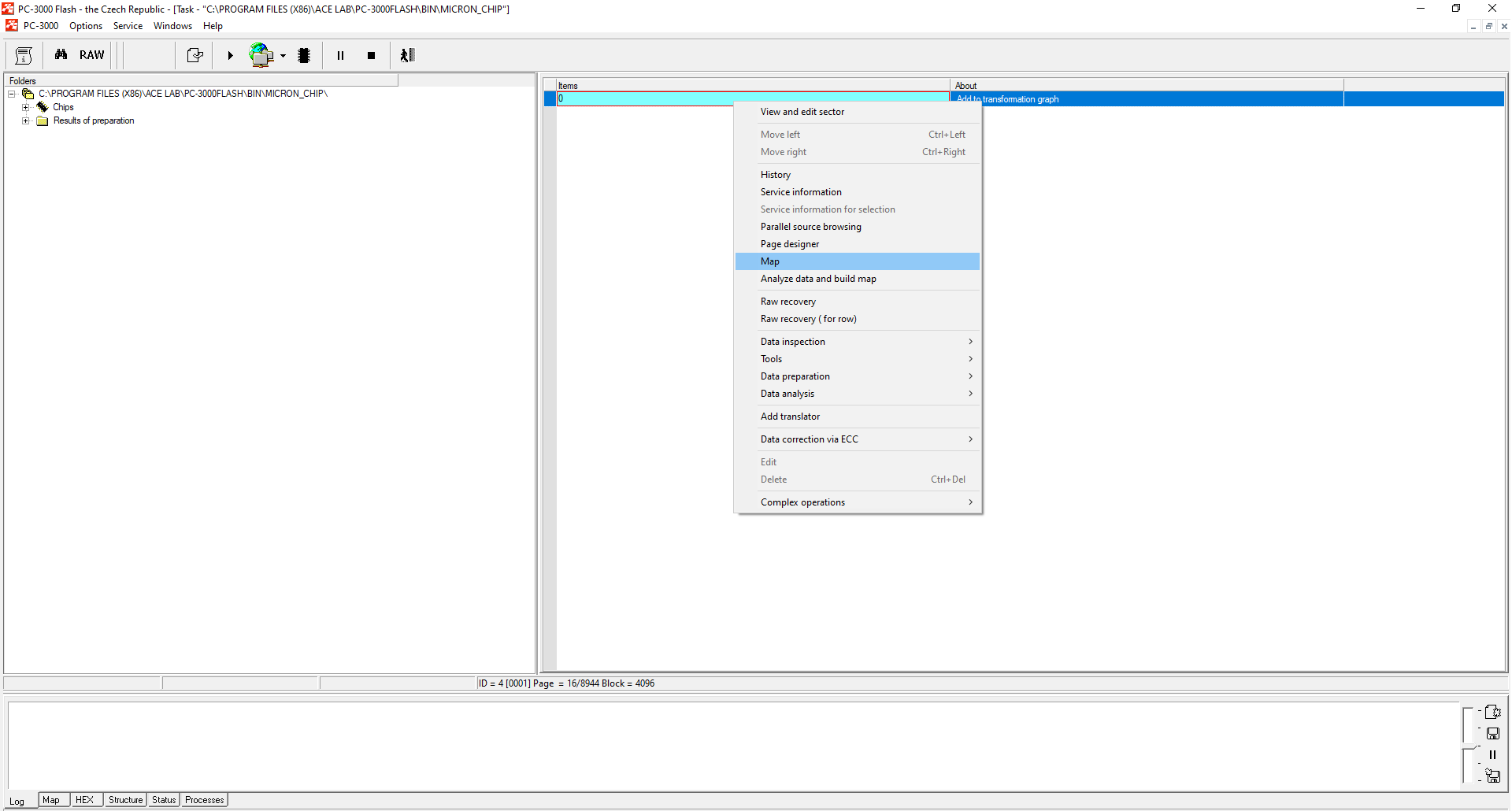
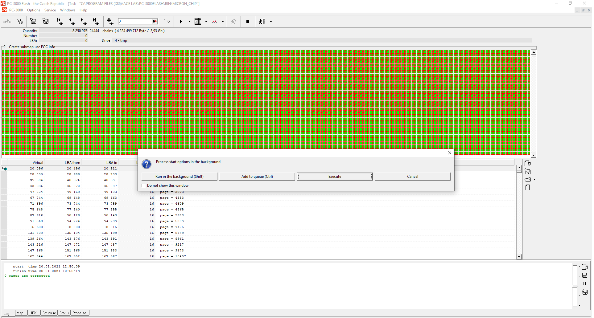
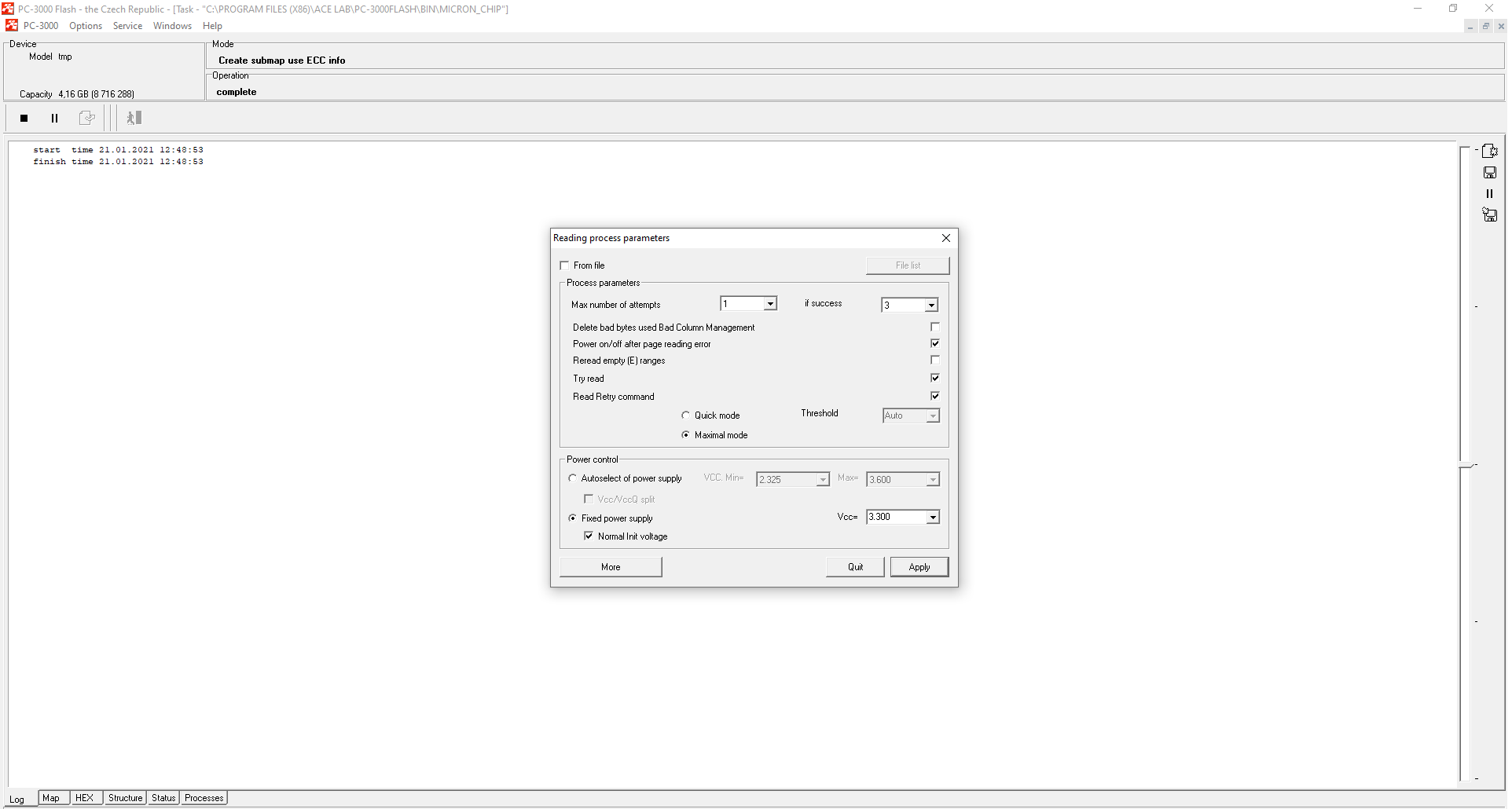
To start the Readout process we need to undertake the following steps:
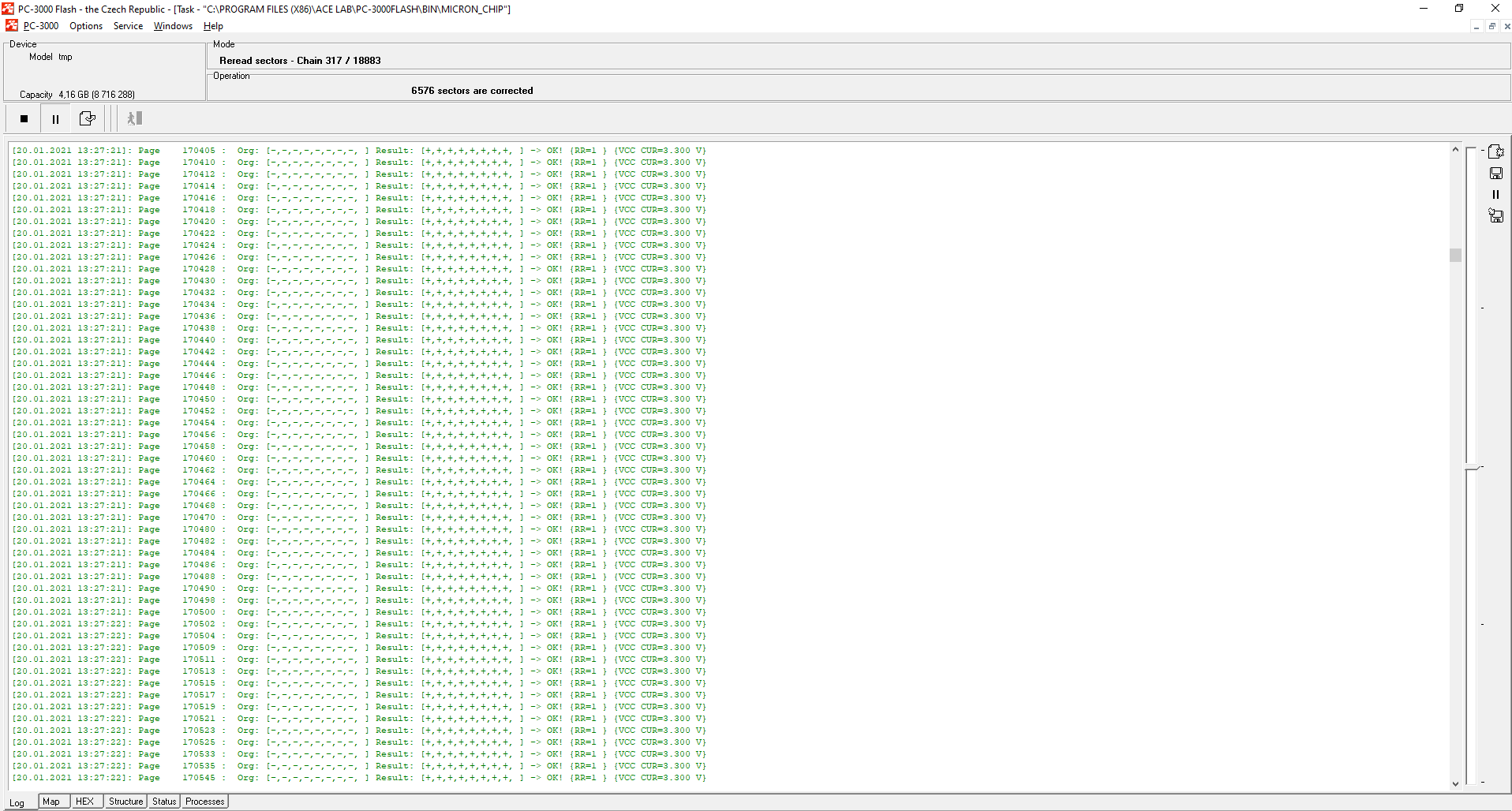
It is better to choose ‘Execute’ than ‘Run in the background (Shift)’ to be able to see how many errors are being fixed right now.
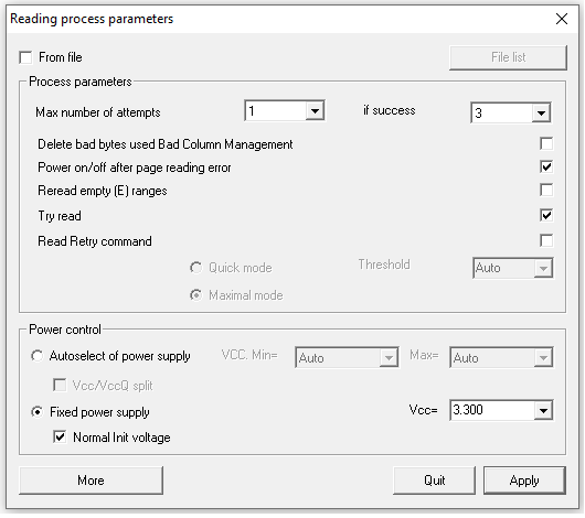
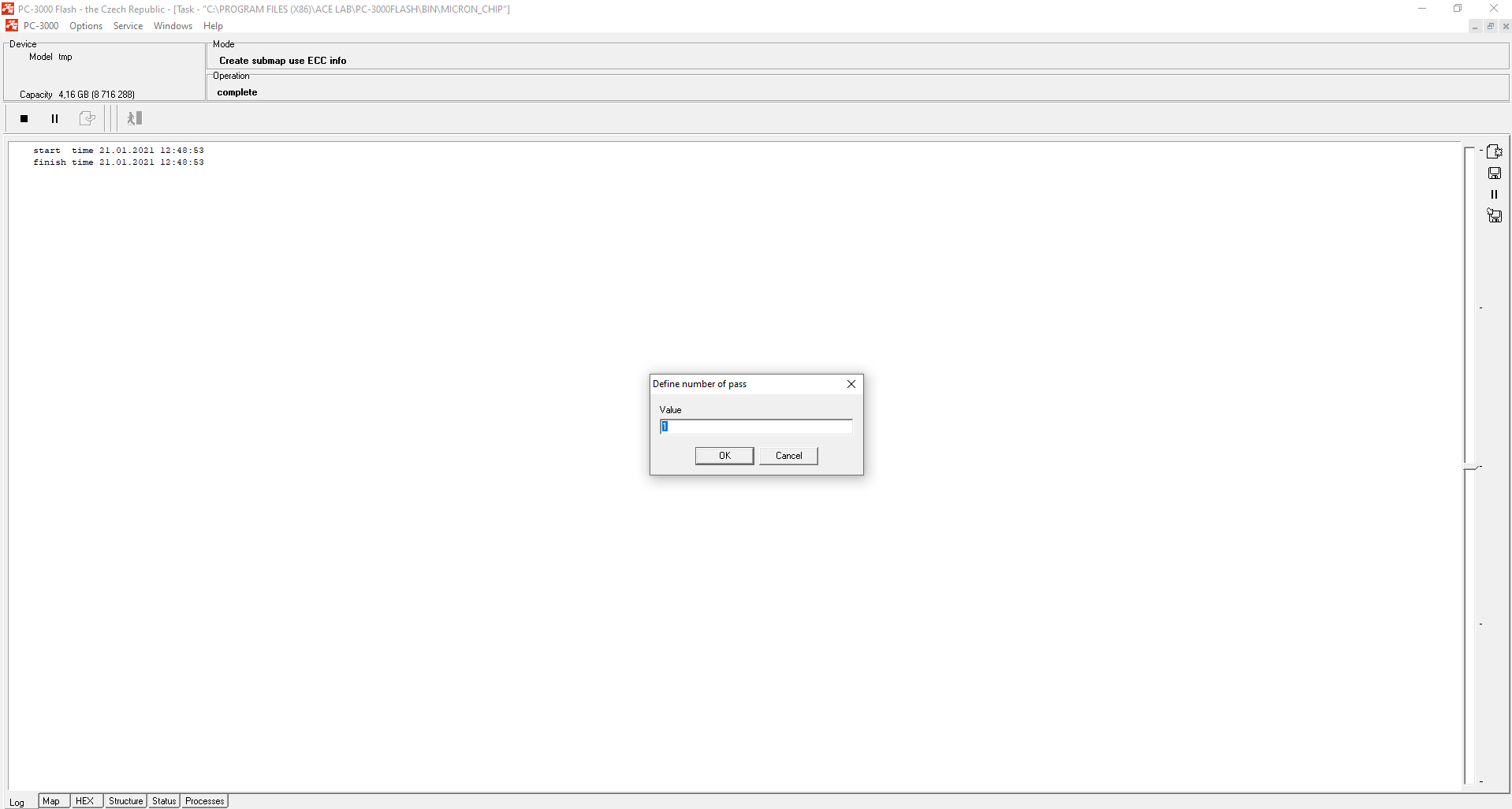
Usually, we recommend using all settings by default. The number of attempts for readout means the number of rereading passes. It is better to keep this number as 1 by default. The ‘if success’ parameter describes the number of additional rereading passes in case if readout helps to fix at least some ranges.
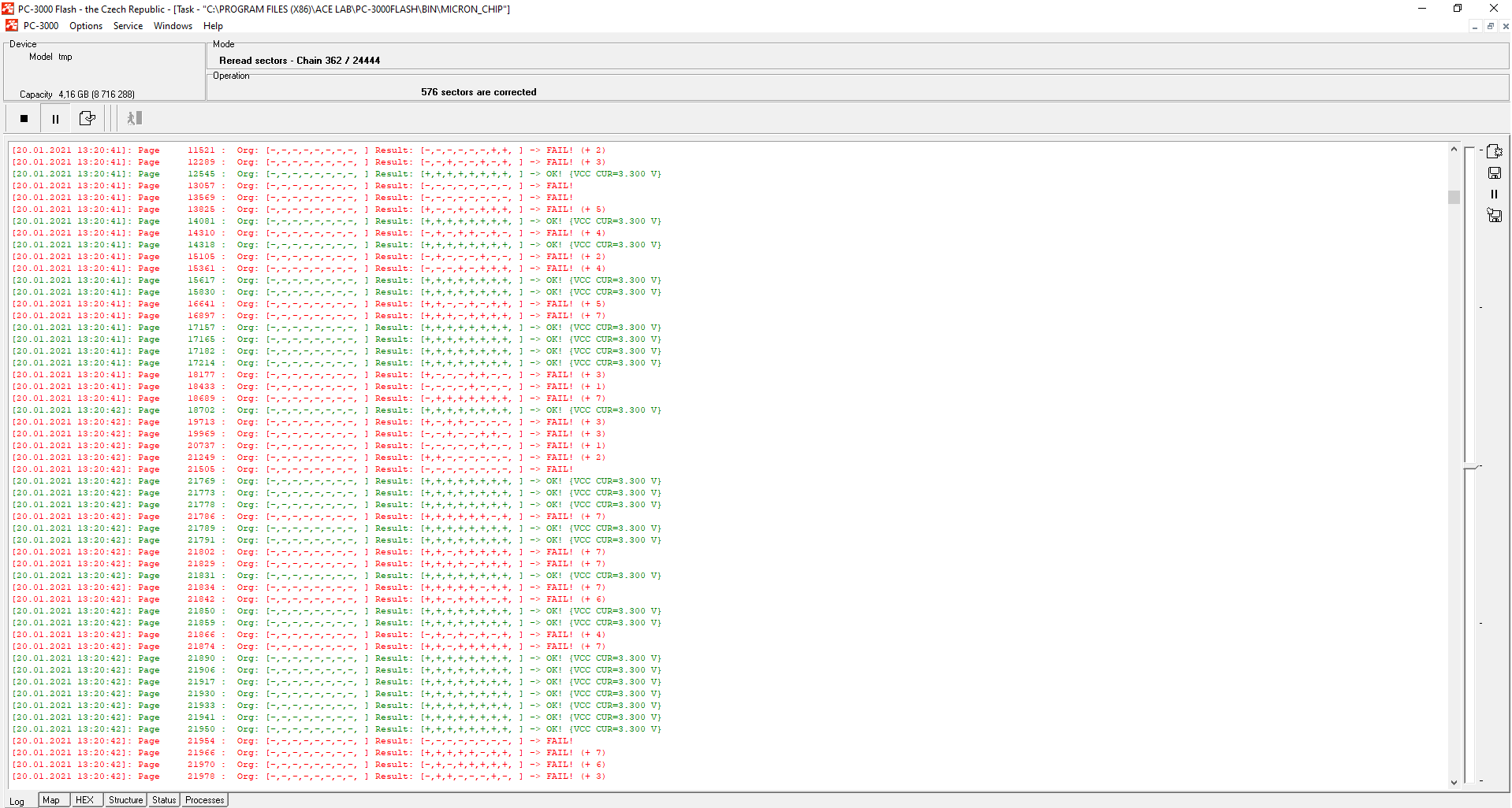
As we can see, it didn’t take long to get the result. Some ranges were corrected, but some of them were not corrected even with readout:
Part 3. Read Retry.
In such cases, we need to use another feature – Read Retry. It is a special NAND chip command which allows the NAND memory chip to change the voltage by itself. The NAND core starts to use different levels of voltage for data fixing. It’s a special self-fixing system that is presented in all QLC/TLC chips and in some modern MLC chips. Right now the PC-3000 Flash supports a lot of ReadRetry modes for a wide number of QLC/TLC/MLC memory chips. With each new weekly PC-3000 Flash resources update, our developers add new algorithms for them.
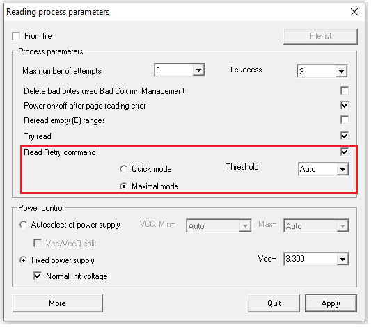
If this Read Retry command checkbox is active, you will be able to get an impressive readout result:
Below you will find one more useful feature for really hard-to-crack cases.
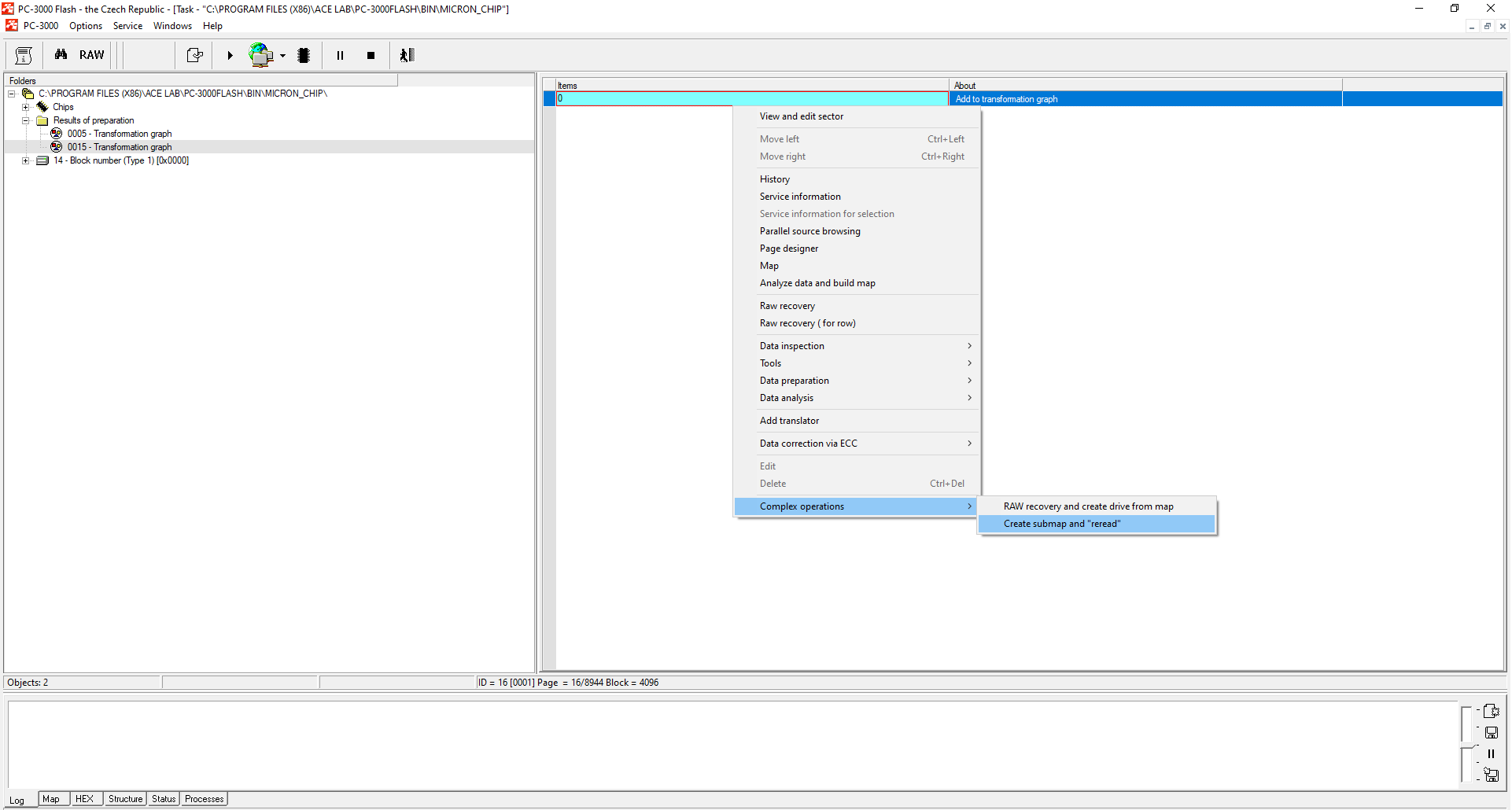
Part 4. Complex operations to save your time.
You can save a little time by using the Complex Operations feature. If you select it, the PC-3000 software automatically builds the map of invalid sectors and asks you about rereading options. Though, you won’t be able to select the number of chains, their order, and so on. So, despite it will save your time by some automatic actions, in the end, you may see that the needed chains have not been corrected.
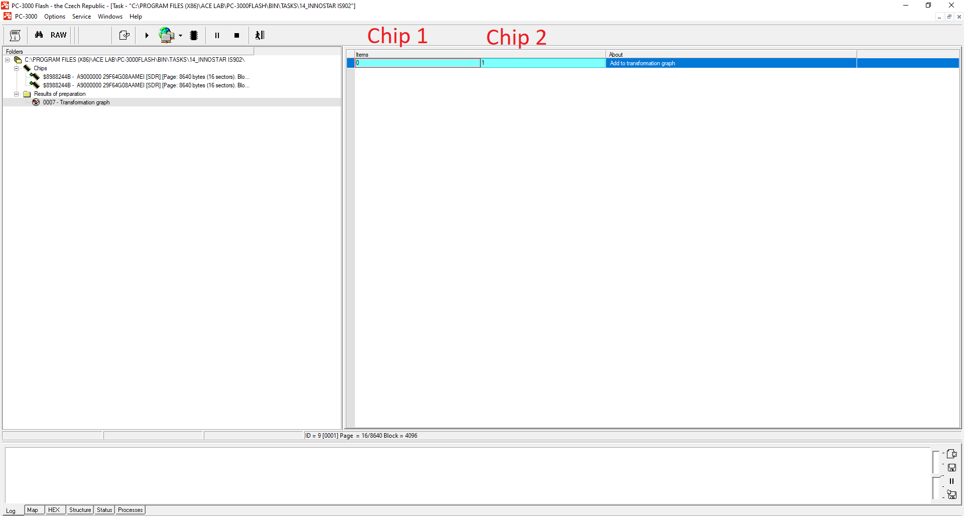
Please remember that if you have a case with more than 1 chip, you need to be sure that you reread the right chip. Sometimes, you may forget to insert the first chip into the PC-3000 Flash Reader again after you finish rereading the dump. So, when the ECC correction is over, you may try to reread the first chip (part 0 on the transformation graph) while having the second one in the Reader. Thus, in the end, you will get two similar parts that should be different. So please pay attention to the chip you have in the reader before starting the rereading process.
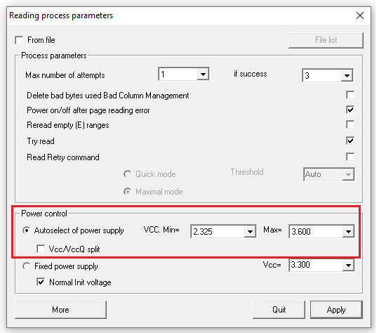
Part 5. Voltage control.
Voltage control can help only in the most problematic cases where the number of bit errors is still very high even after the ECC correction and rereading procedure. Basically, voltage control is a sort of a ReadRetry operation, but in the manual mode. Instead of the chip setting the voltage by itself, we set our own voltage for reading each page in the NAND chip using software control.
Each chip knows the temperature at which it is working right now. Depending on the temperature, the voltage of the chip changes too. Here you can see the table with the approximate value of the temperature and voltage. Sometimes values in this table can shift due to internal problems of the chip, and due to wrong voltage, you won’t be able to reread sectors.

Please note that this option is available only in:
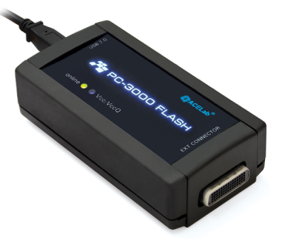
► PC-3000 Flash Reader 3.0 + power adapter (previous generation)
► PC-3000 Flash Reader 4.0 (the newest generation, the power adapter is already integrated)
How to set Voltage Control?
When all possible error fix preparations had been made but the number of errors is still around several hundreds of MB, we should try to use voltage control. Usually, if a NAND memory chip supports ReadRetry, we should not use different voltages – the best result will always be provided by ReadRetry!
But sometimes it can happen that your chip does not support the ReadRetry method. That’s why you need to try to detect the voltage range and to start the correction procedure.
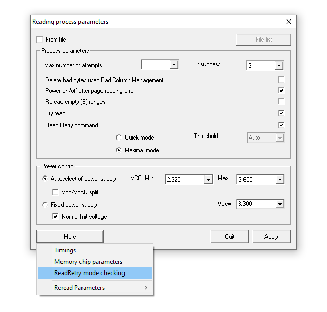
After you fixed ECC, made readout, and built a map of bad sectors, you need to go to the rereading menu and select the next feature:
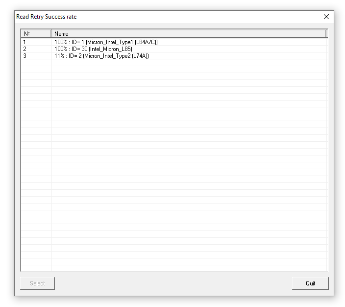
Please remember that if you click ‘More’ and then ‘ReadRetry method checking’, you will be able to check the ReadRetry success rate and choose the best one. In most cases, it automatically chooses the best variant, but sometimes you need to do it manually.
Now the ReadRetry option has appeared
Part 6. Temperature control.
Sometimes, you will not be able to get good rereading results even after rereading with voltage control. What can you do in such cases?
There is one more way to get better rereading results by ‘playing’ with the temperature. For some memory chips, very cold temperature (-15°С…-20°С) may help to increase the electric transfer inside chips to provide the best possible results.
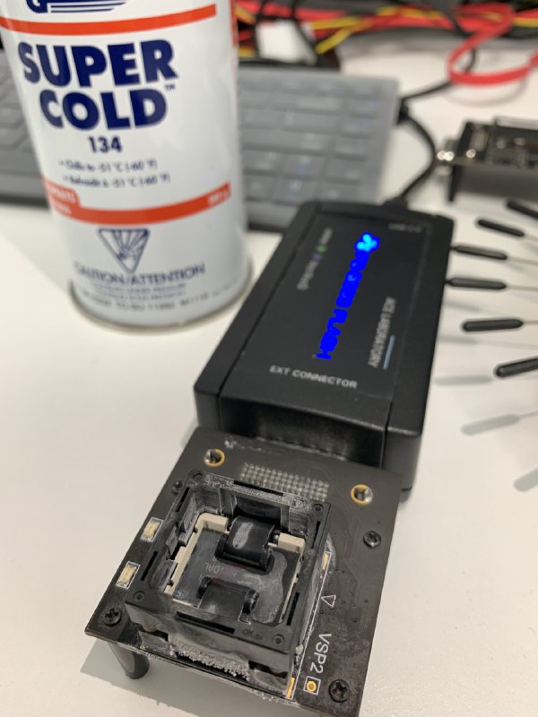
Picture by CapitalDataRecovery
In some cases, you can try to heat up the chip. If you heat it up to +80°C…140°C, you will also get good results of rereading.
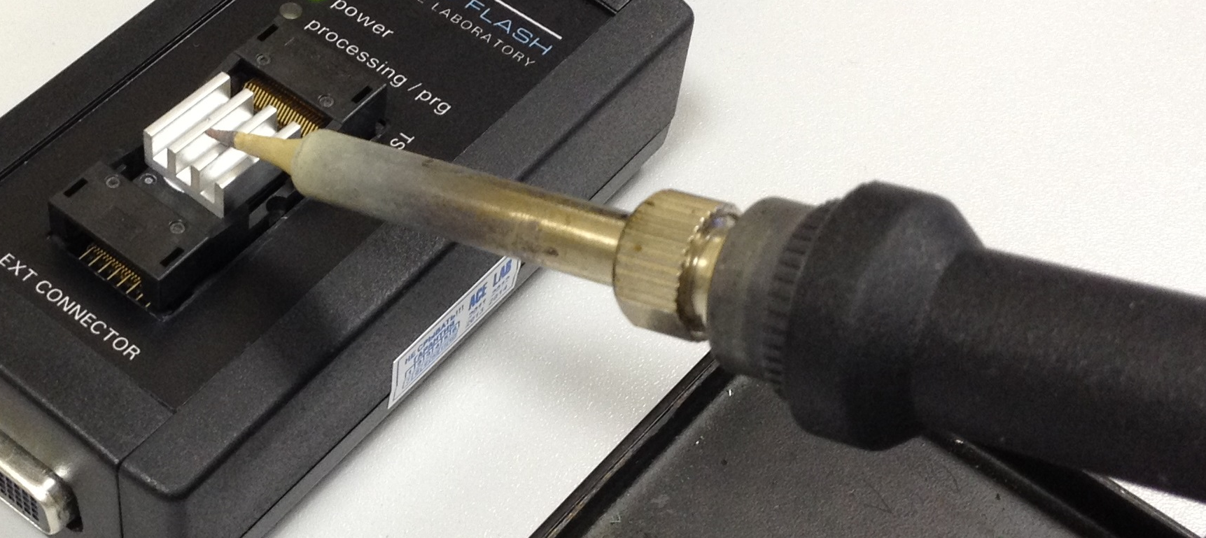
But you should be careful – high temperature can melt the plastic cover and damage the reader.
For more information on how to reduce the risks of damaging your chip, reader, etc, please follow this link.
Let’s summarize the main points:
- Detect and correct ECC only on the Preparation Graph
- Sometimes you need to use additional features to detect and correct ECC (BadBytes, XOR, or Page Transformation)
- To have a good recovery result, the number of bit errors should be less than 5%, and the number of uncorrected chains should be no bigger than 200-300
- Use Rereading if you have a lot of bit errors
- If your chip supports the ReadRetry method, use it instead of other options
- Voltage control will be useful in cases when a NAND Chip does not support ReadRetry
- If your chip does not support ReadRetry, try to use MORE – ReadRetry Mode Checking (this way works only for modern QLC/MLC/TLC chips)
- In some AU, SSS, Phison, and SM cases, you can use Reread Map Generator Tool to save your time.
- In some cases when even voltage control can’t help, you can try to “play” with the temperature.
Have good luck with your Flash data recovery cases and feel free to contact our Technical Support department in case of any questions!


 (9 votes, average: 3.78 out of 5)