

As you know Western Digital drives have a SATA or an USB interface (2.0 or 3.0).
For work with the USB drives better to connect them to PC-3000 via SATA, ’cause USB connection have a restrictions and a lot of preparations can’t be performed via USB interface.
Of cource you can use the compatible SATA board for USB WD drives based on USB v. 2.0.
But what about USB drives based on USB v. 3.0…
Or maybe you haven’t or don’t want to purchase a compatible SATA board for your USB WD drive (on USB v. 2.0)
In this article I would like to tell you how to find a pins for soldering a SATA adapter to the USB WD drives (not depends on version of USB PCB).
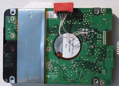
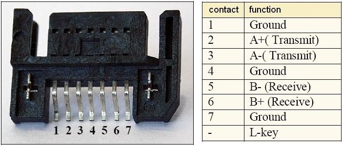
Here is the original SATA connector that we can use for soldering to the USB PCB:
So, how to find a correct pins?
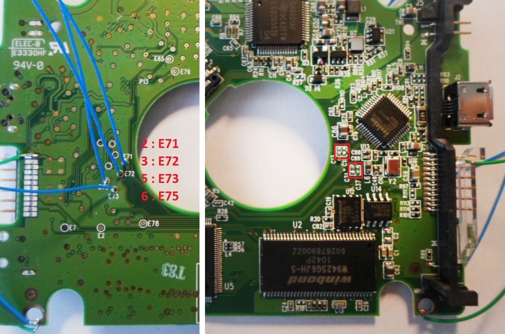
First of all we should find 4 capacitors near USB connector on the tracks from the Main IC chip to the USB controller.
These capacitors are operate a USB bridge and if we are not desolder them then the SATA connector will not work.
Let’s take a look an example:
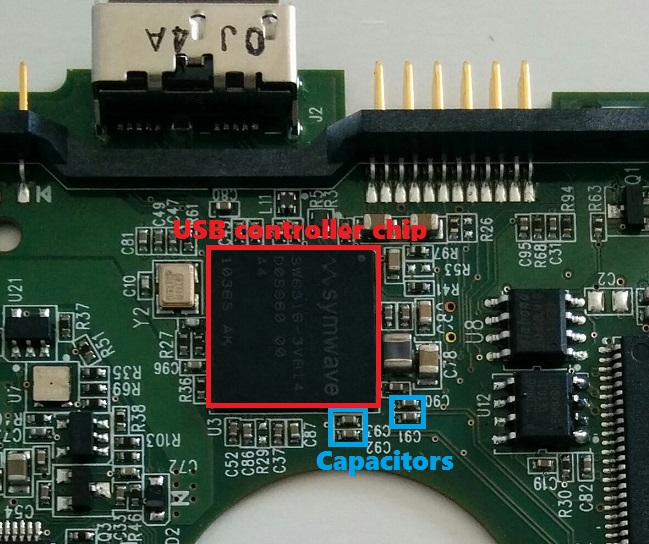
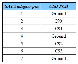
This USB PCB have a Symwave controller chip and Capacitors are marked by “C90”, “C91”, “C92” and “C93” text.
We need to unsolder them and solder the SATA adapter to the points via these tracks on the pcb (near the capacitors).
So, as we can see on the image with the adapter (showed above) we should solder 2, 3, 5 and 6 pins of adapter to the pcb and 1, 4, 7 adapter pins to the Ground.
Pins 2 should be soldered to the minor marked text point on the PCB. In this case it’s “C90”. All other SATA adapter contacts soldering from the minor text to the major.
In this case we have following soldering sequence:
For soldering ground wire you can use any screw on the PCB.
Please note that soldered wires should be no longer than 1-1,5 inchs.
Below you can see example of the soldered SATA adapter to the USB PCB:
Please remember that:
- The power supply control still provides via USB cable (which should be connected to the USB pcb and directly to PC)
- Wires should be no longer than 1-1.5 inchs
- Capacitors should be unsoldered
Remember that you can contact the Technical Support department regarding this or other issues.

Excellent! brilliant!! Thanks a lot
thank ! very good job!
hello
you wrote that must be solder to “1, 3, 7 adapter pins to the Ground.” But when I read the table, Ground pins are 1, 4, 7?
Thank you, the article is modified.
How can I apply this another WD like WD10JMVW with board number 771961 I think it is not clear enough
Could you please contact us at ts.acelaboratory.com with particular questions about the drive you’ve got?
What happens if wires are longer than you have recommended?
Drive can remains in busy forever
GOOD
How do you identify the points where you will solder the Pin 2, 3, 5 & 6? Must the soldering be performed following the serial sequence E71, E72, E73, E75 or are there case where the PCB has maybe E2, E6, E7, E15?
In most drives the pins are E71, E72, E73, E75
Hi!
Thx fo the article.
Access to the disk via the SATA interface is now available. But the data is not deducted. It seems it is encrypted. Is it possible to restore it using the PC-3000?
Thank you!
Yes. Possible.
Start from point 12.
http://blog.acelaboratory.com/pc-3000-hdd-how-to-solve-sed-problem-in-25-wd-drives.html
I’ve a WD5000BMVV-11GNWS0. When I connect via USB, led power on, but PC doesn’t recognize it (tried differents cables and PC). After about 30sec, led start blinking forever. Is there any possibility to use this method to recovery my data?
Why not? Of course!
At least this method allows to you investigate this drive.
Of corse if it’s spinning at all.
Thanks for the reply. I’ve read all data is encrypted and are only readable by usb? Is it true?
Most probably your drive is SED:
https://blog.acelaboratory.com/pc-3000-hdd-how-to-solve-sed-problem-in-25-wd-drives.html
Conatc Technical support service in case you need any assistance:
https://ts.acelaboratory.com/